Hello! Welcome back to our course on radioelectronics.
In our last lesson, we established the fundamental concepts for describing any antenna: its radiation pattern, gain, and impedance. We learned that these parameters are crucial for understanding how an antenna interacts with electromagnetic waves and how it connects to a circuit.
Today, we will apply that knowledge to one of the most important and widely used antennas in radio engineering: the half-wave dipole. This lesson will cover its physical structure, current distribution, radiation pattern, and key electrical characteristics. By the end, you will understand why this simple antenna is a fundamental building block for many more complex designs.
1. The Structure of a Half-Wave Dipole
The half-wave dipole is, in its simplest form, a straight electrical conductor with a total length of approximately half a wavelength () of the signal it is designed to transmit or receive. The conductor is split at its center, where a transmission line is connected to feed it.
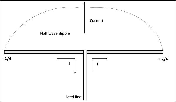
The key to the dipole's operation is the standing wave of current that forms along its elements when driven by a sinusoidal source. Because the ends of the antenna are open circuits, the current must be zero at these points. The current is at its maximum at the center feed point. The distribution of the current's magnitude along the antenna's length (-axis) is sinusoidal, forming a single half-cycle of a sine wave.
Given your background in radiophysics, you'll recognize this as a classic standing wave pattern with defined boundary conditions. The current distribution can be described by the equation:
where is the peak current at the feed point (), is the wavenumber, and is the position along the antenna from to .
2. The Radiation Pattern
The accelerating charges that constitute the current on the dipole are what radiate electromagnetic waves. The specific sinusoidal distribution of this current results in a very distinct and predictable radiation pattern.
The radiation pattern of a half-wave dipole is shaped like a toroid (a doughnut), with the antenna itself passing through the center of the hole.
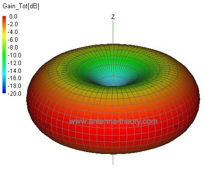
This toroidal shape has important practical implications:
- Maximum Radiation: The antenna radiates most of its power in the plane perpendicular to its axis (the "broadside" direction).
- Nulls: There is zero radiation along the axis of the antenna (off its ends). You cannot communicate with a dipole antenna by pointing its end at the target.
- Omnidirectionality: If you orient the dipole vertically, it radiates equally in all horizontal directions. This makes it very useful for applications like FM radio broadcasting.
This pattern is a significant improvement over the theoretical isotropic radiator from our last lesson, as it focuses energy into a useful plane rather than spreading it in all directions.
3. Key Characteristics: Impedance, Resonance, and Gain
Now, let's connect the dipole to a circuit and quantify its performance using the concepts from our previous lesson.
Impedance and Resonance
The impedance seen at the feed point of an antenna is critical for matching it to the transmission line. For a true half-wave dipole (where the length is exactly ), the feed-point impedance is approximately:
Here, we see two components:
- Radiation Resistance (): This is the desirable part, representing the power being converted into electromagnetic radiation.
- Reactance (): This is an inductive reactance, representing energy stored in the near field.
For maximum power transfer, we want the antenna to be resonant (). The positive reactance tells us that a true half-wave dipole is slightly too long to be perfectly resonant. In practice, the antenna is shortened by about 5% to cancel this inductive reactance. A physically shortened dipole (with ) becomes resonant, and its impedance becomes purely resistive:
This value is very close to the 75 Ω characteristic impedance of some coaxial cables, making it a practical antenna to match.
Gain and Directivity
By focusing its energy into a toroidal pattern, the half-wave dipole achieves a directive gain over an isotropic radiator. The maximum gain of a half-wave dipole is approximately:
This means that in its direction of maximum radiation, the half-wave dipole provides 1.64 times the power density of an isotropic source fed with the same input power. This 2.15 dBi value is a fundamental benchmark in antenna engineering, and the gain of many other antennas is often compared to it using the unit dBd (decibels relative to a dipole).
4. Deeper Dive into the Half-Wave Dipole
To consolidate these concepts and explore them in more detail, please study the following resources. The first provides a clear, illustrated overview, while the second offers more mathematical depth and practical graphs that align with your background.
This document from Ansys, titled 'The Half-Wave Dipole: Design', provides an excellent and concise summary of the dipole's structure, current distribution, and radiation pattern. It uses clear diagrams to illustrate the key concepts we've just discussed.
Please read the entire PDF. It is short and will effectively reinforce your understanding of the dipole's current structure, its far-field radiation pattern, and its characteristic impedance and directivity.
After reviewing the fundamentals, the following resource will provide a more rigorous look at the dipole's properties.
The Wikipedia article on the dipole antenna contains detailed sections that are highly relevant. It includes the mathematical expressions for the fields and provides excellent graphs showing how impedance changes with length.
Please read the following three sections: 'Half-wave dipole': Focus on the equations for current and the far-field electric field, which mathematically define the behavior we've described. 'Impedance of dipoles of various lengths': Pay close attention to the graphs showing the resistive and reactive parts of the impedance versus antenna length. This visualizes why a true half-wave dipole is inductive and must be shortened for resonance. 'Radiation pattern and gain': This section reinforces the toroidal pattern and provides the standard gain figures.
Conclusion
The half-wave dipole is more than just a piece of wire; it is a resonant structure that efficiently transforms a guided electrical signal into a precisely shaped electromagnetic wave. Its simplicity, predictability, and good performance make it a cornerstone of antenna theory and practice.
Key Takeaways:
- A half-wave dipole has a physical length of approximately and is fed at the center.
- It supports a sinusoidal standing wave of current, which is maximum at the center and zero at the ends.
- Its radiation pattern is a toroid (doughnut shape), with maximum radiation perpendicular to the antenna and nulls off the ends.
- A resonant half-wave dipole has a purely resistive impedance of approximately 73 Ω and is achieved by making the antenna slightly shorter than a true .
- It has a characteristic gain of about 2.15 dBi over an isotropic source.
In our next and final lesson of this module, we will explore what happens to these radiated waves after they leave the antenna. We will investigate the different electromagnetic wave propagation modes—such as ground waves, sky waves, and line-of-sight—that determine how radio signals travel from the transmitter to the receiver.