Hello! Welcome back to our course on radioelectronics.
In our previous lesson, we explored how to create an Amplitude Modulation (AM) signal by varying a carrier's amplitude in proportion to a message signal. We established that the information, , is contained within the signal's envelope, and that for distortion-free recovery using simple methods, the modulation index must be less than or equal to 1.
Today's lesson addresses the crucial next step: recovering the original message from the modulated wave. Our learning outcome is to understand AM Demodulation using an Envelope Detector. We will analyze the circuit, its principle of operation, and the critical design choices that ensure the message is recovered accurately.
1. The Envelope Detector: Concept and Circuit
The goal of demodulation is to extract the envelope from the incoming AM signal, . The most common method for standard AM is the envelope detector, a circuit prized for its simplicity and low cost. It consists of just three basic components: a diode, a capacitor, and a resistor.
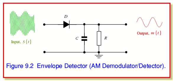
The operation of this circuit is best understood by considering the charging and discharging of the capacitor, which is controlled by the diode.
Chapter 5 Amplitude Modulation
To understand the operation in detail, please read the following section from the 'Chapter 5 Amplitude Modulation' notes by Dr. Fernando N. de Oliveira.
Please read the section titled 'Envelope Detector' (Section 5.4.4). Focus on the description of the 'Charging capacitor' and 'Discharging capacitor' cycles. This will explain how the diode and RC network work together to trace the signal's envelope.
As you've just read, the process can be summarized as follows:
- Charging: During the positive cycles of the high-frequency carrier, when the input voltage of the AM signal is greater than the voltage across the capacitor, the diode is forward-biased. It acts like a closed switch, allowing the capacitor to charge up rapidly towards the peak voltage of the AM wave.
- Discharging: As the carrier wave's voltage drops below the voltage stored on the capacitor, the diode becomes reverse-biased and acts like an open switch. The capacitor then slowly discharges through the load resistor .
This charge-discharge action causes the capacitor voltage, , to follow the peaks of the AM signal, effectively tracing its envelope.
2. The Critical Role of the Time Constant
The performance of the envelope detector hinges entirely on the choice of the RC time constant, . This value must be carefully selected to satisfy two competing requirements.
Requirement 1: Follow the Carrier
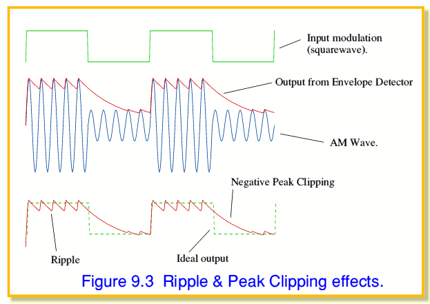
The capacitor must discharge slowly enough that its voltage doesn't drop significantly between consecutive peaks of the high-frequency carrier. If it discharges too quickly, the output will have a large "ripple" at the carrier frequency, which is unwanted noise. To avoid this, the time constant must be much larger than the carrier period ().
Requirement 2: Follow the Envelope
Conversely, the capacitor must discharge quickly enough to follow the envelope as its amplitude decreases. If the time constant is too long, the capacitor voltage won't be able to track the falling edge of the envelope, especially when the message signal is changing rapidly. This results in a distortion known as negative peak clipping or diagonal clipping. To avoid this, the time constant must be much smaller than the period corresponding to the highest frequency component in the message signal, .
The Design Trade-off
Combining these two conditions gives us the fundamental design rule for an envelope detector:
This inequality highlights the core engineering trade-off. It also shows why this method works well only when the carrier frequency is significantly higher than the maximum message frequency (), which is almost always the case in broadcast AM.
The following resource provides a slightly more mathematical look at these distortions and reinforces the importance of the time constant.
For a deeper look at the practical issues of ripple and negative peak clipping, please read this material from 'The Envelope Detector' by Jim Lesurf.
Read the entire page, starting from the second paragraph ('The circuit relies upon...'). Pay close attention to the discussion of 'Ripple' and 'Negative Peak Clipping' and the final condition derived for the time constant au.
The image below, from the resource you just reviewed, provides an excellent visualization of these two types of distortion.
3. Final Step: DC Blocking
The output from the RC network, , is a close approximation of the signal's envelope, which we know from the previous lesson is . This is the original message signal riding on a DC offset equal to the carrier amplitude, .
To recover the original message signal, which typically has an average value of zero (like an audio signal), this DC component must be removed. This is easily accomplished by passing the signal through a DC-blocking capacitor (i.e., a simple high-pass filter). This final stage is shown in Figure 5.20 of the first resource you read ("Chapter 5 Amplitude Modulation").
Conclusion
In this lesson, we have deconstructed the process of AM demodulation with an envelope detector. You now understand how this simple circuit works and the critical engineering trade-off involved in its design.
Key Takeaways:
- An envelope detector recovers the message signal by using a diode to charge a capacitor to the peaks of the AM wave and a resistor to allow it to discharge, tracing the envelope.
- The circuit's performance is governed by the RC time constant ().
- The time constant must be chosen to satisfy the condition to minimize both carrier ripple and negative peak clipping.
- A final DC-blocking capacitor is needed to remove the DC offset from the carrier and recover the original message signal .
- The simplicity and effectiveness of this demodulator are the primary reasons why standard AM includes a large carrier component, despite the power inefficiency we discussed in the last lesson.
Having covered the fundamentals of modulating and demodulating a signal's amplitude, we will next turn our attention to a different paradigm. In the upcoming lesson, we will begin our study of Frequency Modulation (FM), where information is encoded in the instantaneous frequency of the carrier wave rather than its amplitude.