
Good to see you again. In the previous lesson, you made an inventory of responsibilities: platform-facing work such as GLFW and OpenGL integration, reusable runtime services, editor-only behavior, and the rules specific to your game. Now we turn that inventory into a picture of the code’s current connections.
The aim is not to design the ideal engine yet. It is to answer, with evidence from your code: which system creates another, which system stores another, and which system directly calls another? Once those relationships are visible, “everything seems connected” becomes a map of specific links that can be inspected and changed deliberately.
By the end, you will have a dependency map of your existing engine, plus a smaller expanded view around Scene if it is currently central.
A dependency map is not a folder tree
A folder tree tells you where files sit. An include graph tells you which headers compile against which headers. Both can be useful, but neither necessarily tells you what happens when your game runs.
Your map should model runtime knowledge and responsibility relationships. Use one directed, labelled line for each relationship you can demonstrate:
| Relationship | Meaning | Typical evidence in C++ |
|---|---|---|
| creates | The source decides to construct the target object or asks a factory to do so. | std::make_unique, new, emplace_back, a factory call, scene deserialization, a spawn method |
| stores | The source retains a reference, pointer, value, or container of target objects beyond one immediate call. | a member field, std::vector, std::unordered_map, component registry, service field |
| calls | The source directly invokes an operation on the target during normal execution. | renderer.Render(...), component->Update(...), window.PollEvents() |
Read a line in the direction of the label:
ApplicationcreatesSceneScenestoresActorScenecallsRenderer
The source node is the one that must know enough about the target to perform that action. That direction matters more than where the data happens to travel. For example, the renderer may read transform data, but if Renderer invokes TransformComponent::GetWorldMatrix(), the call relationship begins at Renderer.
A single pair of systems can have more than one relationship. If Scene constructs actors, retains them in a container, and invokes their per-frame update, show three labelled connections rather than compressing them into a vague “manages” line.
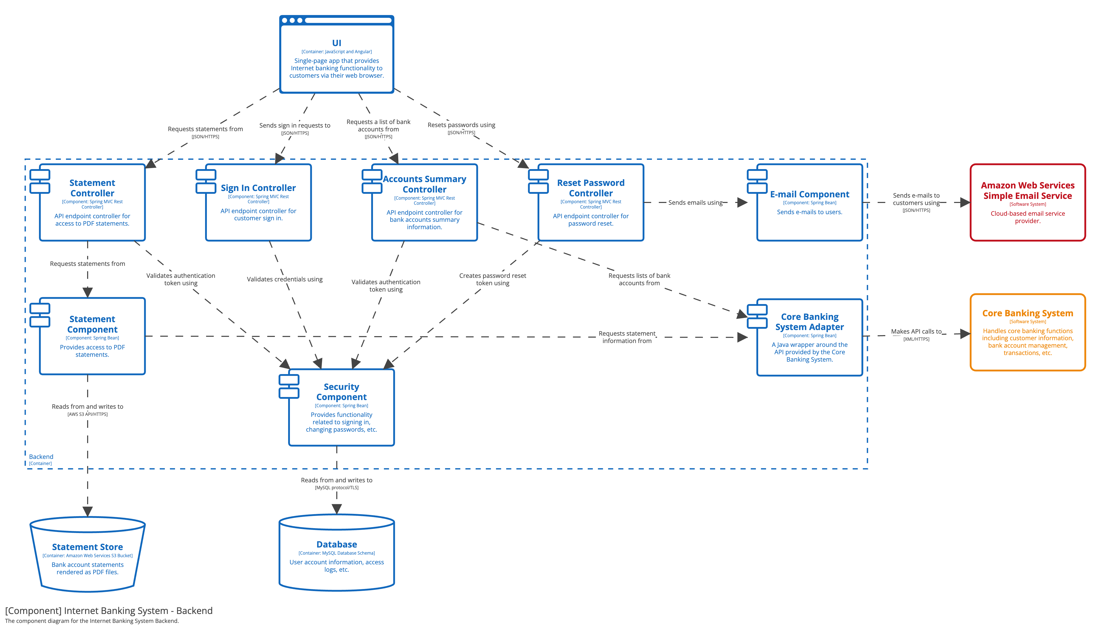
The banking diagram is a presentation model, not an architecture to copy. Its useful lesson is that a box called “Backend” is not enough: the diagram names the components inside it and labels what each connection means. Your engine map should do the same for Scene, renderer, input, collision, editor tooling, and Photon integration.
Keep the scope practical. At this stage, nodes should usually represent:
- a major class that orchestrates behavior, such as
Application,Scene, orRenderer; - a meaningful subsystem, such as collision, asset loading, editor UI, or networking;
- an external boundary, such as GLFW, OpenGL, ImGui, or Photon;
- an important base interface when it determines the direction of calls, such as
Component.
Do not add std::vector, maths helpers, every getter, or every individual mesh as nodes. A useful first map is usually 10–20 nodes, not 200.
Make the three relationships unambiguous
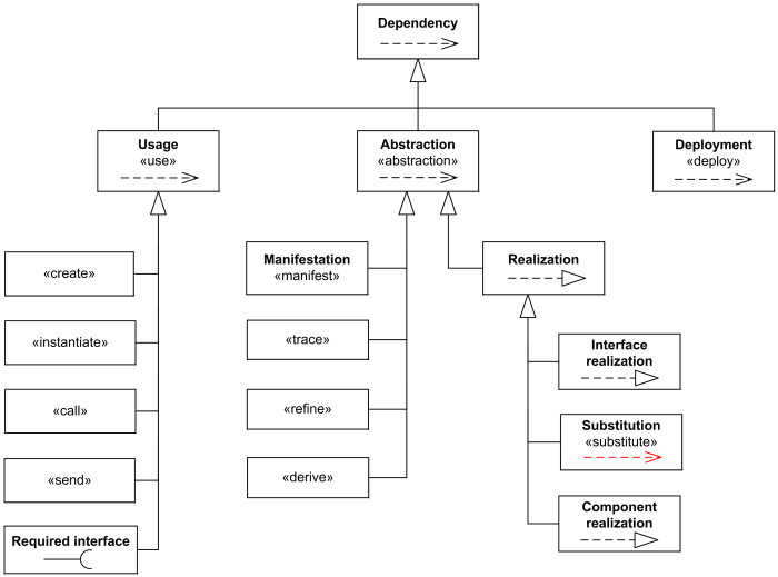
UML has formal notation for these ideas, but your immediate goal is clarity, not perfect UML compliance. A plain directed line with a visible verb label is sufficient. If you later want conventional notation, the important rule remains the same: the line points from the client—the thing that depends—to the supplier—the thing it uses or creates.
UML Class Diagrams - Graphical Notation Reference
Read this reference from UML-Diagrams.org for a concise vocabulary for dependency, usage, creation, association, and composition. Focus on what each relationship claims; do not spend time trying to make your map formally complete UML.
In the “Dependency” and “Usage” material, read dependency notation. Notice that the tail is the client and the arrowhead is the supplier. Then, in the “Usage” and “Create” material, read usage and creation. Map the source’s direct method invocations as calls, and constructor, spawn, factory, or deserialization operations as creates. Finally, in “Composite Aggregation (Composition),” read the composition passage. Use it only to sharpen the distinction between retaining an object and owning its lifetime; the exact ownership decision comes in the next module.
Calls: temporary operational dependence
A calls edge means an operation in the source invokes an operation provided by the target. It is normally temporary: the source may borrow the target as a parameter, obtain it through another object, or hold a non-owning pointer to it. The map does not yet decide lifetime.
Examples that may exist in your project:
- the main loop calls
Scene::Update; - a scene or update coordinator calls
Actor::Update; - an actor calls the enabled components’ update functions;
- a player controller calls collision queries;
- the renderer calls a graphics backend;
- editor UI code calls ImGui functions;
- the application calls GLFW event polling and buffer swapping.
Be precise about intermediaries. Suppose the actual structure is:
Scene::Updateiterates actors.- Each
Actor::Updateiterates its components. - Each component update runs its own behavior.
Your map should show Scene calling Actor, then Actor calling Component. Do not draw Scene calling every component merely because the call ultimately occurs during Scene::Update. The intermediate Actor is architecturally meaningful.
Stores: structural knowledge, not automatically ownership
A stores edge means the source retains the target after the current statement or function returns. That makes it a strong signal of structural coupling.
Examples:
Scenestores actors instd::vector<std::unique_ptr<Actor>>;Actorstores components in a vector, map, or registry;Rendererstores resource handles, render queues, or a backend reference;- an editor selection model stores the selected actor identifier;
- a camera rig stores a reference or handle to its followed actor.
For this lesson, write stores even if you have not yet proved whether the relationship is owning. Add the member name and type as evidence:
ScenestoresActor—m_actors: std::vector<std::unique_ptr<Actor>>
That field strongly suggests ownership, but the next module will treat ownership and destruction rules rigorously. A raw pointer member such as Actor* m_selectedActor is still a stores relationship on this map, but likely non-owning and lifetime-sensitive.
Creates: authority to bring something into existence
A creates edge identifies where an object enters the object graph. It often reveals why a class has become too powerful.
Creation can happen through more than new:
Applicationconstructs the window, renderer, and initial scene at startup.- A scene loader creates actors and components from level data.
Scene::CreateActororSpawnActorconstructs an actor.- An editor menu creates a new actor in edit mode.
- Photon session logic creates a local or remote player representation.
- A resource manager constructs a mesh or material when loading an asset.
Record the real creator, not only a wrapper method. If Scene::CreateActor forwards to an ActorFactory, show both calls and the factory’s creation authority. That distinction may later help you move spawning out of Scene without changing all its callers at once.
Build the current-state map from evidence
Create a file such as:
docs/architecture/current-dependency-map.md
This is an observation document. Avoid renaming, moving, or “cleaning up” code while mapping. A confusing map is useful evidence; a prematurely improved map can hide the reason you needed the refactor.
1. Start with the runtime spine
Put your application entry point or main-loop owner at the top. Then identify only the major systems it initializes and invokes. Likely candidates, based on the prototype you described, are:
- application / main loop;
- GLFW window and input integration;
Sceneor world;- actor and component storage;
- collision service or collision code;
- renderer and OpenGL backend;
- runtime camera and character camera rig;
- editor UI, editor camera, and editor selection;
- Photon integration;
- asset/resource loading.
Use the actual names in your source code. If Scene directly owns a Renderer, write that; do not replace it with a future RenderSystem you have not built.
Here is a deliberately generic shape, not a claim about your implementation. Replace every name and every relation with evidence from your own code; delete edges that prove false.
The verify labels are intentional. A map must describe reality, including uncertainty. Replace each one with a file, member, or function reference before treating it as established fact.
2. Inspect construction paths first
Search for these in your codebase:
- constructors of major subsystems;
make_unique,make_shared,new,emplace, andpush_back;- methods named
Create,Spawn,Load,Initialize,Setup, orAddComponent; - the point where scene loading, play mode, and Photon join callbacks create objects.
For every creation relationship, make an evidence note:
| Source | Relationship | Target | Evidence | Confidence |
|---|---|---|---|---|
Application | creates | Scene | main.cpp, initial scene setup | Confirmed |
Scene | creates | Actor | Scene::CreateActor | Confirmed |
Actor | creates | Component | Actor::AddComponent<T> | Confirmed |
| Photon callback | creates | remote player actor | callback or message handler | Verify |
Do not infer that a class creates something only because it later stores it. A Scene might receive an actor built by a loader, factory, or editor command. Creation authority is worth locating accurately.
3. Inspect member fields for stored relationships
Next, read headers and class definitions. Focus on fields that refer to significant engine objects, not local variables inside a single function.
Record:
- the source class or subsystem;
- the target type;
- the field name;
- the exact storage type;
- whether ownership is known, inferred, or unresolved.
For example:
| Source | Stores | Field evidence | What the map can safely say |
|---|---|---|---|
Scene | actors | m_actors: std::vector<std::unique_ptr<Actor>> | Retains actors; likely owns them |
Actor | components | m_components: ... | Retains components; inspect destruction path later |
SpringArmComponent | target camera | CameraComponent* m_camera | Retains a non-obvious relationship; ownership unknown |
| editor selection | selected actor | Actor* m_selected or ActorId m_selected | Editor state knows about a runtime actor |
| renderer | graphics backend | member reference or pointer | Renderer depends structurally on platform/backend work |
An important rule: a store edge is not proof that the source should own the target. It only proves that the source has lasting knowledge of it. Later, the storage type, destruction order, and reload behavior will determine the ownership rule.
4. Trace direct calls from the main loop outward
Now follow the code that runs once per frame. You will trace the complete frame in the next lesson; here you only capture the direct calls that establish dependency direction.
Start at the loop and note calls such as:
- polling window or device events;
- updating the loaded scene;
- applying editor controls;
- rendering the world;
- rendering ImGui;
- swapping buffers or presenting;
- pumping Photon/network callbacks.
Then expand the calls inside Scene::Update, Actor::Update, Renderer::Render, and any other coordinator. For each edge, capture the caller, callee, and function name:
Scene::UpdatecallsActor::UpdateActor::UpdatecallsComponent::UpdatePlayerControllerComponent::UpdatecallsCollisionWorld::...Renderer::Rendercalls OpenGL backend methods
A virtual call is still a call dependency. If Actor only knows the base Component interface, map Actor calling Component, then list known concrete implementations in a note. This prevents your first map from exploding into a web of every component subtype.
5. Expand Scene rather than hiding it
Since Scene currently manages much of the engine, give it a focused sub-map after the top-level map. The purpose is not to accuse Scene of being wrong; it is to see exactly what it knows.
Use a table before making lines:
Scene operation or field | Relationship type | Target | Evidence to record |
|---|---|---|---|
| actor container | stores | actors | field and container type |
CreateActor | creates | actor | function and factory path |
| update dispatch | calls | actors or systems | exact callee |
| render dispatch | calls | renderer or meshes | exact callee |
| direct keyboard polling | calls | GLFW/input wrapper | exact function |
| editor camera switching | stores/calls | editor camera or editor state | fields and methods |
| ImGui panels | calls | editor UI / ImGui | exact function |
| Photon callbacks | calls/creates/stores | networking and gameplay objects | callback path |
If one Scene method both polls GLFW, changes editor state, runs gameplay behavior, and renders, represent each distinct outgoing relationship. The density around Scene is the information you need. Do not simplify it merely because the resulting map looks uncomfortable.
Keep the map honest: direct, inferred, and unknown
Dependency maps become misleading when they turn assumptions into facts. Add a confidence marker to every line or maintain a companion evidence table.
| Marker | Meaning | Example |
|---|---|---|
| Confirmed | You saw the field, constructor, or direct call. | Renderer::Render invokes OpenGL wrapper functions. |
| Inferred | The relationship is likely, but you have not reached the source yet. | A Photon callback probably reaches player spawn logic. |
| Unknown | You know a connection exists but do not yet know how. | The editor viewport selects runtime actors, mechanism unclear. |
Three common traps are especially relevant to engine code:
- Do not confuse includes with runtime relationships. A header may include another only for a type declaration, templates, or convenience. Conversely, a runtime relationship can be hidden behind an interface, event callback, or service locator.
- Do not collapse callbacks into normal direct calls. If Photon invokes your registered callback, note the registration and callback separately. It is a real dependency, but not necessarily a normal frame-loop call.
- Do not turn desired boundaries into current boundaries. If you want player input to go through an input abstraction but
PlayerControllerComponentcurrently calls GLFW directly, draw the GLFW relationship. The gap is valuable refactoring evidence.
Doxygen can provide supporting static views once your manual map has identified the systems worth investigating. In particular, it can generate include graphs, class usage relations based on member types, and call/caller graphs. Treat this as a cross-check, not as the architecture itself.
Read the Doxygen manual overview to see which kinds of static relationships a documentation tool can surface. The goal is to understand its limits: generated graphs can accelerate discovery, but they do not replace checking runtime meaning in source code.
In the opening bullet list, read include graphs, then continue through call and caller graphs. Compare those graph types with your three labels: includes are compilation evidence, member-type usage can support stores, and call graphs can support calls. None alone reliably establishes architectural ownership or game-level meaning.
Do not pause the refactor planning to configure documentation tooling unless it already exists in the project. For a compact engine you know firsthand, source search plus an evidence-backed manual map is often faster and more trustworthy.
Your finished artifact
At the end of this session, your document should contain:
- A top-level map showing the application, runtime world/scene, platform boundaries, editor code, and networking boundary.
- A focused
Scenemap showing every major system it currently creates, stores, or calls. - A relationship legend:
creates,stores,calls. - Evidence notes for every significant connection.
- Uncertainties and surprises, particularly:
- editor code directly depending on gameplay state;
- gameplay components directly calling GLFW, OpenGL, ImGui, or Photon APIs;
- systems that both create and update objects;
Sceneconnections that cross platform, runtime, editor, and game-specific responsibility categories;- pairs of nodes that each store or call the other.
The last item is not yet a list of bugs. It is a list of locations where future ownership and boundary decisions will matter most.
Key takeaways
A current dependency map answers three concrete questions: who creates whom, who retains whom, and who directly calls whom. Label every connection with one of those verbs and support it with a field, function, constructor, or callback location in the code.
Keep the map at meaningful subsystem or orchestrating-class granularity, then expand Scene separately rather than letting its complexity disappear into one large box. Distinguish current facts from inferred links, and do not mistake header includes or desired future abstractions for runtime architecture.
Next, you will use this map to trace one complete frame: from input, through gameplay and transforms, into collision and rendering.
Can't find a good explanation? Sign up and we'll make it for you
Sign up