
Hello! Welcome to your sixth and final lesson in the "Thermodynamics: Energy and the First Law" module.
In our last lesson, we mastered the application of the First Law of Thermodynamics to closed systems, where the mass is fixed. We analyzed the four fundamental processes for ideal gases: isochoric, isobaric, isothermal, and adiabatic.
Today, we shift our focus from closed systems to open systems, where mass flows across the system boundary. This is essential for your aerospace goals, as most propulsion components—jet engines, rockets, and their internal parts—are open systems.
Our learning objective is to apply the steady-flow energy equation (SFEE) to components like nozzles, diffusers, and heat exchangers. We will derive this crucial equation and then use it as a powerful tool to analyze the energy transformations within these devices.
1. From Closed to Open Systems: The Steady-Flow Energy Equation
In a closed system, we tracked the energy of a fixed amount of mass. In an open system operating under steady-flow conditions, the mass inside the system is constant, but there is a continuous flow of mass through it. The properties of the fluid at any point within the system do not change with time. Think of a jet engine running at a constant throttle setting—air and fuel flow in, and exhaust flows out, but the engine's internal state is stable.
To analyze these systems, we need to adapt the First Law to account for the energy carried in and out by the flowing mass. This gives us the Steady-Flow Energy Equation (SFEE).
Thermodynamics - 5-3 Energy analysis of steady flow devices
To understand the concept of steady-flow and see how the energy balance is formulated, please watch the first part of this video from 'Engineering Deciphered'. It clearly explains the principles and derives the general form of the SFEE.
Watch from the beginning to 08:13. Focus on: The definition of a steady-flow device: properties are constant in time, but can vary by location. The mass balance for steady flow: mass in equals mass out (\sum \dot{m}_{in} = \sum \dot{m}_{out}). The energy balance, which leads to the full SFEE.
As the video shows, for a single-inlet (1), single-outlet (2) steady-flow device, the SFEE can be written as:
Where:
- is the rate of heat transfer into the system (Power, e.g., kW).
- is the rate of shaft work done by the system (Power, e.g., kW).
- is the mass flow rate (kg/s).
- is the specific enthalpy (kJ/kg).
- is the velocity (m/s).
- is the elevation (m), and is the acceleration due to gravity.
The term is the specific kinetic energy, and is the specific potential energy.
A key takeaway is the importance of enthalpy (). In open systems, enthalpy () conveniently groups the internal energy of the fluid () and the "flow work" () required to push the fluid into and out of the system.

2. Application: Nozzles and Diffusers
Nozzles and diffusers are fundamental components in aerospace propulsion.
- A nozzle is a device designed to increase the velocity of a fluid at the expense of its pressure. The exhaust of a rocket or jet engine is a classic example.
- A diffuser does the opposite: it slows down a fluid, increasing its pressure. The inlet of a jet engine is a diffuser, slowing the incoming air before it enters the compressor.
We can simplify the SFEE for nozzles and diffusers by making a few reasonable assumptions:
- No Shaft Work: (they have no moving parts).
- Negligible Heat Transfer: They are typically short, and the fluid passes through quickly, so there is little time for heat transfer. We often assume they are adiabatic, so .
- Negligible Potential Energy Change: The change in elevation from inlet to outlet is usually zero or insignificant, so .
Applying these simplifications to the SFEE:
Rearranging gives the core relationship for nozzles and diffusers:
This equation shows a direct conversion between enthalpy (related to temperature and pressure) and kinetic energy (related to velocity).
Thermodynamic Foundations – Introduction to Aerospace ...
The following resource from Embry-Riddle Aeronautical University specifically discusses these devices in an aerospace context. It includes a helpful worked example.
First, read the subsection 'Nozzles & Diffusers'. Pay attention to how pressure and velocity change in subsonic flow. Then, skip down to the section 'Energy in Flow Devices' and review the worked example 'Check Your Understanding #1 – Flow through a nozzle'. This demonstrates the direct application of the simplified energy equation.
Now, let's see how this is applied in more detailed problems. The following video provides excellent step-by-step examples.
Steady Flow Systems - Nozzles and Diffusers | Thermodynamics | (Solved examples)
This video from 'Question Solutions' walks through several solved examples for nozzles and diffusers. This will solidify your understanding of how to apply the formulas.
Watch the three worked examples from 04:19 to the end. Notice how the enthalpy values are found: Example 1 (Air): Treats air as an ideal gas, where enthalpy change is found using specific heat: \Delta h = c_p \Delta T. Example 2 (Refrigerant) & 3 (Steam): Uses property tables to look up enthalpy values at the given states, just as we did for closed systems.
Test your understanding!
Steam enters a nozzle at a pressure of 4 MPa and a temperature of 400°C with a velocity of 60 m/s. It exits at a pressure of 2 MPa and a temperature of 300°C. The process is adiabatic.
Using the simplified SFEE for an adiabatic nozzle, calculate the exit velocity .
You will need these enthalpy values from a steam table:
- At 4 MPa, 400°C: kJ/kg
- At 2 MPa, 300°C: kJ/kg
Show answer
-
Start with the simplified SFEE for an adiabatic nozzle:
-
Rearrange to solve for the unknown, :
-
Substitute the values. Be careful with units! Enthalpy is in kJ/kg, while kinetic energy is in J/kg (). We must convert kJ to J by multiplying by 1000.
- kJ/kg = 3,214,500 J/kg
- kJ/kg = 3,024,200 J/kg
- m/s
The exit velocity of the steam is approximately 620 m/s. The large increase in velocity is due to the significant drop in enthalpy.
3. Application: Heat Exchangers
A heat exchanger is a device that transfers thermal energy from one fluid to another without them mixing. Radiators in cars and condensers in refrigerators are common examples. In aerospace, they are used to cool oil using fuel or to manage cabin air temperature.
Let's analyze a heat exchanger by drawing a control volume around the entire device.
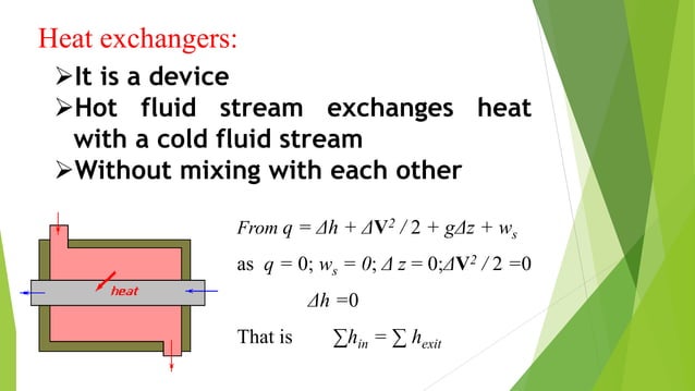
As the diagram shows, we typically make the following assumptions:
- Adiabatic: The entire device is well-insulated, so there is no heat transfer to the surroundings (). The heat transfer is internal, between the two fluids.
- No Work: .
- Negligible Kinetic and Potential Energy Changes: The velocities and elevations of the fluids do not change significantly.
With these assumptions, the general SFEE for a system with multiple inlets and outlets () simplifies to:
Or, the total rate of enthalpy leaving the device equals the total rate of enthalpy entering it.
Chapter 10 THE FIRST LAW APPLIED TO STEADY FLOW ...
For a clear definition and derivation of the energy balance for heat exchangers, please read the following section from a thermodynamics textbook.
Read the section titled 'Heat Exchangers'. Focus on how the general multi-stream energy equation (10.4) is simplified to equation (10.19) for an adiabatic heat exchanger. This shows that the energy lost by the hot fluid is gained by the cold fluid.
For a typical heat exchanger with two fluids (A and B), the energy balance becomes:
This simply states that the rate of energy lost by the hot fluid equals the rate of energy gained by the cold fluid.
Conclusion
In this lesson, we bridged the gap from closed to open systems, which is critical for analyzing the propulsion and power systems you are interested in. You learned how to apply the First Law of Thermodynamics to steady-flow devices, resulting in the powerful Steady-Flow Energy Equation (SFEE).
Key Takeaways:
- The SFEE is the cornerstone for analyzing open systems, accounting for energy transferred by heat, work, and the mass flowing through the device.
- The full SFEE is: .
- For nozzles and diffusers, the equation simplifies to a trade-off between enthalpy and kinetic energy: .
- For an adiabatic heat exchanger, the energy balance shows that the enthalpy lost by the hot fluid is gained by the cold fluid: .
- Simplifying the SFEE depends on identifying the primary function of a device and making reasonable assumptions about which energy terms are significant and which are negligible.
Preview of the Next Module:
We have now completed our study of the First Law. It's a powerful conservation principle, but it tells us nothing about the direction a process can occur or the quality of energy. For example, a hot cup of coffee cools down in a room, but we never see a cool cup spontaneously draw heat from the room to get hot. The First Law would allow this, but it never happens.
In our next module, we will explore the Second Law of Thermodynamics. This will introduce the fundamental concept of entropy, which governs the direction of natural processes and sets the ultimate limits on the efficiency of engines and power cycles.
Can't find a good explanation? Sign up and we'll make it for you
Sign up