
Good to see you again. In the preceding lesson, you selected and documented a main tooling direction, parting strategy, shutoffs, and possible side actions. This lesson turns that tooling intent into evidence: the CAD must now show adequate wall behavior, releasable draft, no unexplained undercuts, and controlled surface quality.
For the assumed ECU base or cover, use the named tooling reference created previously, such as AX_TOOL_MAIN. By the end of this lesson, you should be able to run a disciplined moldability-inspection pass in Onshape, interpret the results rather than merely collect screenshots, and map the same inspection logic to CATIA V5/V6.
1. Inspection is a design decision, not a color-map exercise
A CAD analysis result is only meaningful when its inputs are controlled. Before opening an analysis tool, record:
- Part and revision: for example,
ECU_BASE, revisionA.03. - Geometry state: the Onshape version or controlled workspace state being inspected.
- Tooling direction:
AX_TOOL_MAIN, including which direction is designated as Side 1. - Requirement source: supplier DFM guidance, internal standard, appearance requirement, or project-specific requirement.
- Acceptance threshold: nominal wall target and permitted local exceptions; minimum draft by feature class.
- Scope: exterior shell, interior walls, sealing rim, bosses, ribs, connector openings, mounting lugs, and any slide-formed feature.
This prevents a common review failure: an engineer changes a draft angle or wall thickness, reruns the analysis, but the screenshot in the review pack still reflects an earlier geometry state or a different pull direction.
A useful principle is:
An analysis identifies geometry needing engineering judgment. It does not replace the requirement, the mold supplier, or validation evidence.
For example, a localized thin region around a snap feature may be intentional and acceptable. A similar-looking thin region at the base of a long exterior wall may create filling, cooling, warpage, or durability risk. The color is only the start of the investigation.
2. Evaluate wall thickness as a distribution, not a single dimension
A wall thickness requirement is rarely “everywhere exactly .” Injection-molded parts contain intended departures from nominal thickness: ribs, bosses, sealing features, local reinforcements, radii, and transitions. The engineering task is to distinguish an intentional and controlled departure from an accidental mass concentration or thin section.
For an enclosure, first identify the nominal shell wall from the part requirements. Then inspect how the real geometry departs from it:
- Are broad shell walls near the intended nominal thickness?
- Do transitions change gradually rather than forming abrupt thick-to-thin steps?
- Do ribs and bosses create hidden thick intersections beneath appearance or sealing surfaces?
- Are thin zones near openings, corners, or draft transitions still structurally and moldably credible?
- Does the local geometry create material “lumps” that will cool more slowly than surrounding shell walls?
The generic range sometimes cited for injection-molded walls is not an ECU-housing requirement. Polymer grade, glass content, flow length, cosmetic requirements, tool cooling, structural loads, and supplier capability must set the actual target. In this course, use the requirement-controlled nominal wall and the gradual-transition logic established in the polymer and DFM module.
Two thickness methods in Onshape
Onshape’s Thickness Analysis provides two main geometric interpretations. They answer related but distinct questions.
Read Onshape’s official “Thickness Analysis” documentation to understand both the workflow and what each result actually measures. This distinction matters when interpreting local colors around ribs, corners, and radii.
In the “Steps” section, read the starting workflow, including selection of the part, use of the color scale, and adjustment of the displayed range. Then read the sections “Rolling ball thickness method” and “Ray thickness method”: compare the rolling ball definition with the ray definition. Finish with “Thickness gradient,” focusing on what the gradient measures.
The methods can be summarized as follows:
| Method | What it measures | Best use | Interpretation caution |
|---|---|---|---|
| Rolling ball | Diameter of the largest sphere that can fit locally inside the solid | Smooth screening of local “throat” regions and overall thickness behavior | It is not always the direct normal distance between inner and outer shell faces |
| Ray | Distance along a ray projected normal to the surface until its first intersection with the solid | Checking shell-like regions where a normal wall distance is meaningful | Results can change sharply near corners, ribs, and complex intersections |
| Rolling-ball gradient | Rate of change in rolling-ball thickness across the surface | Finding abrupt mass changes or transitions | A high value is a review flag, not automatically a defect |
| Ray gradient | Rate of change in ray thickness | Locating abrupt shell-thickness variation | Corners and topology changes can create expected discontinuities |
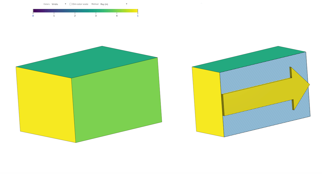
The ray method is often intuitive for an enclosure wall: on a broad shell face it approximates the through-wall distance you would expect to measure in section. But at a corner, the ray may hit a nearby intersecting face rather than the nominal opposite wall. Do not treat every narrow-band color change at a fillet as a manufacturing defect.
The rolling-ball result is continuous by construction, so it often gives a more stable overview of geometry. Yet its value near a rib root or tight internal corner can represent the available internal sphere diameter, not the nominal shell thickness you placed in the model.
Reading a thickness map correctly
Use a staged interpretation:
-
Set a purposeful display range.
Set the lower and upper color limits around the nominal target and your permitted deviation. A broad default range can hide a meaningful thin zone; an overly narrow range can make normal radii appear alarming. -
Use the dimmed-color option as a triage view.
Regions outside the selected range should visually stand out. This is useful for a first pass, but it does not establish acceptability. -
Investigate each out-of-range region in section view.
Create a section through the feature and use Measure. Determine whether the result comes from:- a legitimate shell wall,
- a rib-to-wall intersection,
- a boss root,
- a fillet or corner condition,
- an opening or shutoff,
- an unintended feature interaction.
-
Classify the result.
Record each case as accepted, accepted with rationale, action required, or supplier review required.
For a wall of draw depth , draft also changes the local dimension. If two opposite walls diverge symmetrically from a neutral interface with draft angle , the separation at depth is approximately:
where is the separation at the neutral plane. If only one wall drafts, the change is approximately . This is why a shell that begins at a valid nominal thickness can become too thin or too thick at the far end after draft is added. Thickness analysis must therefore be rerun after significant draft changes.
Plastic Part Modeling (Tutorial)
Watch the relevant sections of Onshape’s “Plastic Part Modeling (Tutorial)” to see draft and thickness inspection used on a modeled plastic part. The tutorial is practical, but treat its numerical examples as demonstrations rather than ECU-specific specifications.
Watch draft setup for the relationship between mold direction, minimum draft, neutral-plane selection, and functional dimensions. Then watch thickness inspection for the Onshape thickness-analysis workflow and the manufacturing consequences of uneven wall sections. Focus on the reasoning: the model is not accepted because colors look uniform, but because deviations are understood.
3. Evaluate draft relative to the declared pull direction
Draft is not simply “a taper on a wall.” It is the angular relationship between that wall and a specific mold-opening direction. If the declared mold split direction changes, the same physical face may change from acceptable to steep or from releasable to undercut.
For the ECU base, begin with AX_TOOL_MAIN, normally normal to the base-to-cover sealing plane in the preliminary concept. Do not select an arbitrary planar face merely because it produces more favorable colors.
Read Onshape’s official “Draft Analysis” documentation before using the result as evidence. It explains what the tool detects and how the two pull-direction sides are represented.
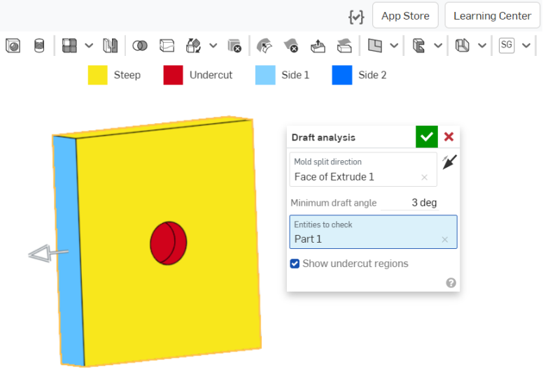
Read the opening section for the purpose of the tool. Then read the explanation below the image on how the result is oriented: the two sides and direction flip. In the Part Studio, repeat this with your own declared tooling direction and hover over at least one face to inspect its exact angle.
A disciplined Onshape draft-analysis pass
In the Part Studio:
- Open Show analysis tools in the lower-right graphics area and select Draft analysis.
- Select the reference defining
AX_TOOL_MAINas the Mold split direction. - Enter the applicable minimum draft angle. Do not use a universal value for all surfaces.
- Select the complete part, then use section views and temporary hiding as needed to expose interior faces.
- Hover over critical faces to inspect actual local angles.
- Save an evidence screenshot showing the part, tooling direction, legend, minimum draft angle, and model revision.
The displayed colors should be read functionally:
| Result type | Typical meaning | Required engineering response |
|---|---|---|
| Side 1 color | Face has acceptable draft toward the positive analysis direction | Confirm this is the intended core or cavity side |
| Side 2 color | Face has acceptable draft toward the opposite direction | Confirm it releases from its intended tool half |
| Steep color | Face does not achieve the configured minimum draft | Add draft, change the neutral plane, revise geometry, or obtain an approved exception |
| Undercut color | Face traps the part for the declared main pull | Redesign, revise parting/shutoff strategy, or document required moving tooling |
The Side 1 and Side 2 colors are not “good side” and “bad side.” They identify opposite release directions. A healthy enclosure commonly displays both, because interior and exterior faces are formed by opposite tool halves.
Feature-specific draft requirements
The generic guideline of to can be a starting point for some untextured plastic faces, but it is not sufficient to release an automotive component. Draft must be assigned by feature function and tooling direction.
| Feature class | What determines the draft requirement |
|---|---|
| Exterior shell | Texture, draw depth, appearance sensitivity, expected cavity side |
| Interior shell | Draw depth, polymer shrinkage, core retention and ejection strategy |
| Ribs and gussets | Their narrow depth, core-tooling access, and local root geometry |
| Bosses and PCB supports | Core-pin release, dimensional function, and sink-control geometry |
| Shutoffs | Steel-on-steel contact, wear, flash risk, machining and venting |
| Connector openings | Main-pull or side-pull strategy, sealing interfaces, mating clearance |
| Slide or lifter features | The slide or lifter pull direction, which is separate from main pull |
A draft fix can create a functional problem if it moves the wrong interface. Neutral-plane selection is therefore an engineering decision. If the sealing rim, connector aperture, or mounting datum must preserve a controlled size, keep that interface neutral and allow a less critical region to change dimension.
When reviewing a drafted feature, check all three conditions:
- Release: Does the face meet the draft requirement in its actual pull direction?
- Function: Is the required mating or locating dimension still correct at the correct plane?
- Wall behavior: Has the draft introduced a thin end, thick end, or abrupt transition?
4. Treat undercuts as a result requiring disposition
The prior lesson established that an undercut is relative to a tooling direction. Draft Analysis provides a direct way to test whether the nominal geometry supports the tooling strategy.
For every red or undercut region found under AX_TOOL_MAIN, assign one of these dispositions:
| Disposition | When it is appropriate | Evidence to retain |
|---|---|---|
| Geometry correction | The undercut is unintended | Updated CAD and a revised passing analysis |
| Parting-line revision | A different core-cavity split can form the feature without moving tooling | Updated parting concept and supplier feasibility check |
| Stationary shutoff | Opposing steel can create the required opening robustly | Shutoff section, draft intent, steel-support review |
| Side action or lifter | The feature is functionally necessary and cannot be resolved otherwise | Pull direction, travel envelope, access, cost and risk record |
| Secondary operation | Mold complexity is disproportionate and post-molding manufacture is feasible | Process, tolerance, cost, and traceability evaluation |
| Approved exception pending supplier DFM | The concept is provisional but a decision is not yet mature | Risk-register entry, owner, due date, and approval status |
Do not clear an undercut from the visual record by changing the analysis direction unless the actual tooling concept also changes. If a connector pocket will be formed by a side action, perform a second draft analysis using that side-action direction. Keep the main-pull analysis as well, because the rest of the part still has to eject in the main direction.
For the ECU base, a credible inspection package might show:
- Main-pull draft analysis using
AX_TOOL_MAIN; - A section through the connector interface;
- A side-pull analysis for a retained slide candidate such as
SA_CONN_01; - A note that the red area is an intentional slide-formed pocket, not an unresolved design error;
- A supplier-review action to confirm slide travel, steel thickness, sealing risk, and tool maintenance access.
5. Surface continuity: inspect the quality of the shape, not only its thickness
Wall thickness and draft inspect the volume of a part. Surface continuity inspects how neighboring faces connect. This matters because a solid can be watertight and still contain an unintended visual kink, an abrupt curvature change, a tiny sliver face, or a poor transition that complicates tool machining.
Three continuity levels are useful:
| Level | Meaning | Typical result |
|---|---|---|
| positional continuity | Faces meet at the same boundary location | No gap, but a sharp edge may remain |
| tangency continuity | Faces meet and have aligned tangent directions | No visible angular kink under normal viewing conditions |
| curvature continuity | Faces meet with matched curvature behavior | Smoother highlight flow and a more refined appearance transition |
Not every connection needs . A deliberate molded edge, a datum break, or a parting-line boundary may correctly be . Many functional transitions need only plus an appropriate radius. Higher continuity is most valuable when surface appearance, reflection quality, or smooth motion is important.
For the ECU enclosure, continuity review should focus on:
- Exterior radii transitioning into broad cover or base surfaces;
- Sealing-rim corners and transitions into local bosses;
- Connector flange blends;
- Mounting-lug roots;
- Regions where draft has modified fillets into conical or irregular surfaces;
- Imported or supplier-provided surfaces used as design references.
What to look for
A continuity problem often appears as one of these conditions:
- A visible highlight line or sudden reflection break across what should be a smooth transition;
- A curvature map with abrupt, isolated bands away from intended edges;
- A local sliver face created by intersecting fillets or late design changes;
- A surface gap or an unexpected free edge in imported surface geometry;
- A radius that collapses, becomes extremely small, or changes unexpectedly after draft;
- A section profile that shows a kink where the design intended a smooth blend.
A smooth-looking shaded model is not enough. Standard shading can conceal subtle tangency or curvature problems, especially under a single lighting condition.
CATIA and Onshape inspection equivalents
The exact CATIA command location depends on V5/V6 configuration and licenses, but the engineering intent is consistent.
| Inspection intent | CATIA V5/V6 approach | Onshape-equivalent approach |
|---|---|---|
| Check release relative to tooling axis | Draft Analysis with selected pull direction and threshold | Draft Analysis under Analysis Tools |
| Find unexpected thin or thick material | Wall Thickness or Thickness Analysis where available | Thickness Analysis using ray and rolling-ball methods |
| Check surface joins and gaps | GSD Connect Checker, boundary inspection, join diagnostics | Inspect face boundaries, use section views and Measure; repair feature logic or imported geometry before relying on the solid |
| Inspect visual smoothness | Zebra, reflection, curvature, or porcupine-curvature analysis where available | Use curvature visualization where available; otherwise inspect with carefully placed sections, face analysis, and controlled visual review |
| Validate critical blends | Surface curvature and tangent analysis, plus section checks | Section views normal to the transition, curvature display if available, and direct measurement of radii and wall offsets |
In CATIA, a practical surface-quality sequence is to inspect the connection using Connect Checker, identify unexpected boundaries, then use curvature or zebra-style analysis to judge whether a nominally smooth blend behaves smoothly. In Onshape, the most reliable baseline without specialist surfacing tools is a combination of section views, inspection of face boundaries, measurement, and controlled visual review. The goal is not to claim identical commands across systems; it is to make the same engineering judgment.
6. A repeatable moldability-inspection workflow
Use the following procedure for each significant molded part. It is suitable for the ECU base now and can be reused later for the door carrier and HVAC components.
Step 1: Freeze the inspected geometry
Create an Onshape version before analysis, using a meaningful name such as:
V_A03_ECU_Base_Preliminary_DFM_Check
Record the Part Studio, part name, and version identifier in the analysis record. In a CATIA/ENOVIA environment, this corresponds to evaluating a controlled revision or maturity-state object, not an uncontrolled local file.
Step 2: Check wall thickness first
Run ray thickness analysis for broad shell regions and rolling-ball analysis for overall screening. Use a section view to investigate every significant outlier.
For each outlier, record the actual local geometry and its disposition. “Expected because of a rib” is not enough; state whether the rib root, local mass, and adjacent cosmetic or sealing surface remain acceptable.
Step 3: Run main-pull draft analysis
Select AX_TOOL_MAIN, set the requirement-based threshold, inspect all external and internal faces, then use section views to reveal hidden regions.
A draft map should show only:
- acceptable faces in the intended side colors;
- deliberately documented parting candidates;
- explicitly dispositioned undercut regions.
Step 4: Check alternative tool directions where needed
For a slide, lifter, or side core, run a separate analysis in that component’s pull direction. Label the screenshot clearly so a reviewer cannot confuse it with the main-pull result.
Step 5: Inspect continuity and local transitions
Review intended smooth blends, critical radii, imported surfaces, and features affected by draft. Check whether the modeled transition supports both the desired surface quality and practical tool machining.
Step 6: Publish a short controlled report
A useful preliminary report can fit on one page:
| Report field | Example content |
|---|---|
| Part and state | ECU_BASE, V_A03_ECU_Base_Preliminary_DFM_Check |
| Tooling direction | AX_TOOL_MAIN, normal to sealing interface |
| Nominal wall requirement | Requirement reference and target band |
| Thickness method | Ray and rolling ball, display range and units recorded |
| Draft thresholds | Exterior, interior, rib, boss, shutoff, and slide-feature thresholds |
| Results summary | Number of accepted regions, exceptions, and open issues |
| Undercut disposition | Shutoff, redesign, side action, or pending decision |
| Surface-quality result | Critical blends inspected; gaps, kinks, or sliver faces identified |
| Evidence links | Screenshots, section views, measurements, supplier DFM feedback |
| Review status | Accepted for next iteration, conditionally accepted, or action required |
The evidence should be legible enough that a manufacturing engineer or supplier can reconstruct what was checked. Include the orientation triad, pull-direction arrow, legend, threshold values, and the revision state of the model.
Key takeaways
A moldability inspection is a connected evaluation:
- Wall thickness must be assessed as a distribution across the real geometry, not as a nominal value in a sketch.
- Ray thickness is useful for shell-like normal distances; rolling-ball thickness gives a continuous geometric screening result. Both require section-based interpretation at corners and feature intersections.
- Draft is always evaluated relative to the declared mold-opening direction. A face can be valid for one pull direction and an undercut for another.
- An undercut is acceptable only when it has a documented manufacturing disposition, such as a shutoff, side action, lifter, redesign, or justified secondary operation.
- Surface continuity concerns the quality of connections between faces. Watertight geometry alone does not prove a smooth, appearance-appropriate, or tool-friendly transition.
- Your final output is not merely a set of color maps. It is a controlled analysis record tied to a CAD version, requirements, tooling directions, exceptions, and actions.
Next, the course moves from geometric manufacturability into physically defensible structural analysis: defining realistic loads, constraints, contacts, idealizations, and material data for a linear-static FEA of a component.
Can't find a good explanation? Sign up and we'll make it for you
Sign up