
Welcome back. In the previous lesson, you created a controlled master-skeleton strategy: shared packaging, mounting, connector, PCB, and sealing references have an owner, a baseline, and downstream consumers. That structure now becomes the starting point for a manufacturing decision: how can the molded part leave the tool?
For an injection-molded component, the tooling direction is not a cosmetic CAD setting. It determines which surfaces need draft, where a visible parting line may appear, whether an opening can be made with stationary tool steel, and whether costly moving mechanisms are unavoidable. For the assumed ECU enclosure, these decisions also affect sealing-land quality, connector packaging, service access, and supplier-tooling feasibility.
By the end of this lesson, you will be able to define a mold opening direction, distinguish a parting line from a shutoff, identify undercuts relative to the selected direction, and document whether a feature is resolved by geometry, a shutoff, or a side action.
1. Begin with the ejection problem
A conventional injection mold has two primary halves:
- The cavity side generally forms much of the exterior of the part.
- The core side generally forms interior volume, bosses, and other inward-facing geometry. The molded part often shrinks onto this side and is ejected from it.
The two sides separate along a chosen mold opening direction, also called the tooling axis, draw direction, or main pull direction. In this lesson, call that direction .
A successful main-pull strategy allows the part to remain intact while it travels away from both mold halves along the opening motion. A surface that blocks that motion is an undercut.
Crucially, an undercut is not an absolute property of a feature. It is a property of a feature relative to a chosen tooling direction.
For example, a lateral window in an ECU housing may be straightforward with a horizontal mold opening direction but become an undercut if the part opens vertically. Conversely, choosing the horizontal direction may make the base’s deep interior, sealing perimeter, and mounting features much harder to mold. Tooling direction is therefore a whole-part decision, not a local-feature decision.
Injection Molding - Undercuts (How to Avoid and Design)
Watch “Injection Molding - Undercuts (How to Avoid and Design)” by Protolabs for a concise visual explanation of why an undercut prevents ejection and the principal ways designers resolve it.
Start with the design options. Focus on the physical reason the trapped sample cannot leave the mold, then distinguish the four responses: shutoffs, parting-line changes, bump-offs, and side actions. Continue with the shutoff redesign to see how opening the material below a snap feature creates room for stationary mold steel. The demonstration uses Fusion 360; focus on the geometry and pull-direction logic rather than the CAD commands.
A useful first-pass classification for every significant face or feature is:
| Classification | Meaning relative to | Typical disposition |
|---|---|---|
| Main-pull face | Can be formed and released by the fixed core and cavity halves | Apply adequate draft and retain it in the main tool |
| Parting candidate | Naturally lies at, or can be moved to, the division between mold halves | Incorporate it into the parting line or parting surface |
| Shutoff candidate | Can be formed where tool steel from opposing halves meets | Add a drafted shutoff condition; confirm tool-steel robustness |
| Undercut | Traps the part relative to main pull | Redesign, relocate the parting line, use a shutoff, or add a moving mechanism |
| Non-molded feature | Is better created after molding | Consider machining, drilling, trimming, or assembly, if justified |
Do not use “side action required” as the default label for every lateral hole. First ask whether the feature can be redesigned as a pass-through, brought to the parting line, or formed by a robust stationary shutoff.
2. Select the mold opening direction before placing the parting line
For the assumed ECU housing base, the most credible initial tooling direction is usually normal to the base-to-cover sealing interface. That is often the direction in which the shell is deepest and most naturally opens.
This does not mean that the tooling axis must equal a vehicle coordinate direction. The ECU may be installed at an angle, upside down, or on a vertical vehicle bracket. The loose component can be oriented in the mold in whichever way best supports molding, ejection, gating, and tooling access.
Use the master skeleton from the previous lesson to define the tooling direction deliberately:
- Start with the published sealing-plane reference, such as
PLN_COVER_MATE. - Create a tooling-axis reference normal to that plane.
- Give it a functional name, for example
AX_TOOL_MAIN. - Record which side is intended to retain the part for ejection.
- Evaluate every relevant face, opening, rib, boss, latch, connector feature, and mounting detail relative to that axis.
For a cup-like ECU base, the interior cavity is usually formed around a core. The open side of the enclosure makes the sealing-interface normal a strong candidate for , because it can form:
- The main internal cavity;
- PCB-support features and internal bosses;
- Most vertical walls;
- The base floor and its reinforcement pattern;
- A continuous perimeter suitable for a controlled separation between the tool halves.
A candidate direction is poor when it causes several of the following:
- Large visible exterior surfaces require awkward or insufficient draft.
- The parting line crosses a sealing land, mounting seat, or critical datum surface.
- Multiple unrelated side actions become necessary.
- Ejector pins would have to contact appearance surfaces or thin flexible areas.
- A deep core has poor stiffness, cooling, or venting potential.
- The geometry creates trapped regions that cannot be cleared during ejection.
A disciplined selection rule
Choose the tooling direction that gives the lowest overall manufacturing risk, not simply the fewest undercuts.
For a visible door trim carrier, appearance may make a particular parting-line location unacceptable even if it avoids a slide. For a sealed ECU housing, flash risk on the gasket land or connector interface may justify a somewhat more complex tool. For an HVAC vane, repeatable pivot geometry and low witness-mark risk can outweigh a nominally simpler pull direction.
At this stage, document the choice as a design assumption, not a final tool release:
| Field | Example preliminary record |
|---|---|
| Part | ECU housing base |
| Tooling-axis ID | AX_TOOL_MAIN |
| Direction basis | Normal to PLN_COVER_MATE |
| Ejection-side assumption | Base retained on interior-forming core side |
| Primary objective | Maintain a robust shell, protected sealing interface, and direct pull for interior features |
| Key risks | Connector opening, exterior retention features, shutoff wear, sealing-land flash |
| Evidence required | Draft analysis, section views, tooling-feasibility review, supplier DFM feedback |
| Status | Preliminary design review baseline |
3. A parting strategy is more than drawing a line around the part
The parting line is the visible trace on the molded part where the mold halves meet. The parting surface is the three-dimensional tooling interface that separates the core and cavity. A flat plate-like part may have a simple planar parting surface; an enclosure often requires a contoured or stepped one.
The parting line matters because it can leave:
- A small mismatch between tool halves;
- Flash if the tool does not close cleanly;
- A visible witness line;
- Local dimensional variation;
- Tool wear at high-pressure contact areas.
For an automotive ECU base, do not casually place the parting line across the functional gasket-sealing land. Instead, a preferred concept is often to route it around an outer edge of the perimeter rim, allowing the sealing land itself to be formed by one controlled tool surface or by a carefully designed core-cavity relationship. The exact strategy must be confirmed with the mold supplier, gasket design, tolerance stack, and ingress target.
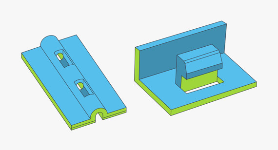
The following visual shows why tool-steel contact can be designed to create openings without automatically adding a moving slide.
A good parting strategy balances five concerns:
| Concern | Practical question |
|---|---|
| Mold release | Can all main-pull surfaces separate from the tool with adequate draft? |
| Function | Does the parting line avoid sealing lands, precision mounting faces, locating datums, and electrical isolation features? |
| Appearance | Can the line be hidden on an edge, shadow line, flange, or non-visible B-side surface? |
| Tooling simplicity | Is the parting surface as simple and robust as the functional geometry permits? |
| Part quality | Are flash risk, venting, filling, weld-line location, and cooling still manageable? |
A parting line may be deliberately non-planar. It can follow a rim, step across a feature, or “zigzag” to meet several local features. But every turn in that path increases complexity, steel matching, inspection effort, and potential flash locations. A complicated parting line is justified only where it removes a more severe issue.
Design Tip: 6 ways to achieve undercut success in molded parts
Read Protolabs’ design note to see how a moved parting line, side action, and telescoping shutoff change the tooling solution for an undercut.
In the subsection “1. Parting Lines,” read the standoff example. Notice that changing the parting line is a whole-tool decision rather than a local sketch edit. In “2. Side-Actions,” read the side action cycle and identify when the slide must retract. Finally, in “5. Telescoping Shutoffs,” read the shutoff guidance, focusing on its warning about draft on contacting tool-steel surfaces.
4. Shutoffs: stationary tool steel solving an apparent undercut
A shutoff is a region where mold steel from one side meets steel from the other side during closing. The contacting steel blocks polymer flow in a controlled area. In the finished part, that can create an opening, slot, window, hook clearance, or other local absence of material.
A shutoff is therefore a tooling condition, not merely an opening modeled in the plastic component.
This distinction is important:
- A rectangular opening in a housing wall is a part feature.
- The drafted, mating surfaces of the core and cavity that form the opening are a shutoff.
- A slide that enters from the side to form the same opening is a side action.
A shutoff can be a lower-cost alternative to a slide when it has sufficient steel support and the mold halves can separate without trapping the part. The surrounding plastic geometry must give the steel somewhere to meet and separate.
Pass-through cores and telescoping shutoffs
A pass-through core is a common shutoff-based solution. Steel from one half passes through an opening region and meets the opposing half. It is especially valuable for through-holes and openings that can be designed to provide a continuous path for the steel.
A telescoping shutoff is a related strategy in which one tool feature projects into the opposing half to create geometry such as a hook or a clip clearance. It can remove the need for a separate moving mechanism when the feature is accessible from the main tool-opening direction.
For an ECU housing, candidate shutoff features can include:
- A connector opening that can be reshaped as a pass-through opening;
- Drain or vent windows at a housing edge;
- A local clearance under a cantilever retention feature;
- A slot that reaches a perimeter or parting region;
- A service opening that does not need a fully enclosed lateral pocket.
Shutoff design cautions
Shutoffs are economical only when they are mechanically sound. Avoid treating them as thin, vertical, zero-clearance CAD walls.
At a preliminary level:
- Put draft on shutoff faces. The Protolabs guidance recommends aiming for at least from vertical where practical.
- Avoid very thin or weak “knife-edge” steel.
- Avoid placing high-pressure shutoffs where the tool is likely to deflect.
- Ensure the shutoff can be machined, vented, cooled, and maintained.
- Locate likely flash at a non-critical location whenever possible.
- Ask the supplier to confirm the final steel condition, minimum land widths, material selection, hardness, and wear treatment.
For the assumed PA66-GF30 ECU housing, do not rely on part flexibility to release a sharp undercut. Glass-filled nylon is stiff and fiber-reinforced; it is a poor candidate for aggressive bump-off behavior. Favor a redesign, a robust stationary shutoff, or a side action where the functional feature truly requires it.
5. Side actions and lifters: moving tooling only where it earns its cost
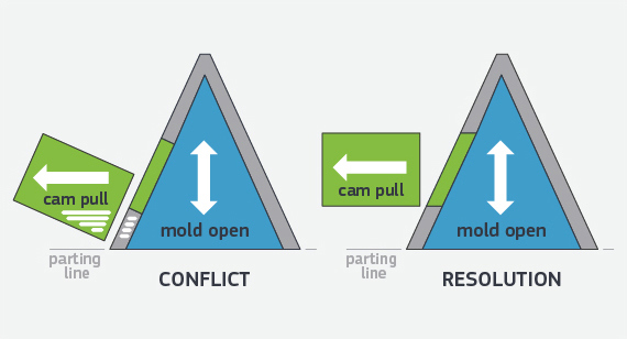
A side action, also called a side core, slide, or cam action, is a movable tool element that travels laterally or at an angle relative to the main opening direction. It moves into position while the mold closes, forms the feature during injection and cooling, and retracts enough to clear the part before ejection.
A side action is appropriate when a feature:
- Is inaccessible from the main core and cavity halves;
- Cannot be brought to the parting line without damaging function or appearance;
- Cannot be formed by a robust pass-through or telescoping shutoff;
- Cannot safely flex past a bump-off;
- Is too functionally important to create in a secondary operation.
An external undercut, such as a lateral aperture with a re-entrant ledge, is often formed by a side core. An internal undercut, such as an inward-facing hook within a deep cavity, may instead require a lifter. A lifter moves with the ejector system at an angle while releasing the trapped internal feature.
The following image emphasizes that side-action motion has to coexist with the main mold-opening motion and the parting-line layout.
For every proposed side action, define more than its direction. A usable preliminary record includes:
| Field | What to document |
|---|---|
| Side-action ID | A controlled identifier such as SA_CONN_01 |
| Feature formed | Connector aperture, lateral latch pocket, undercut slot, or other named feature |
| Pull direction | Direction of slide travel relative to AX_TOOL_MAIN |
| Retraction requirement | Travel needed to clear the feature before part ejection |
| Space claim | Envelope required for slide body, cam pin or actuator, and maintenance access |
| Feature draft | Draft relative to the side-action pull direction, not only the main pull |
| Tooling impacts | Cost, cycle time, cooling difficulty, wear, flash risk, and cavity-count implications |
| Product impact | Witness marks, local wall-thickness changes, sealing risk, service interference |
| Alternative considered | Redesigned opening, moved parting line, shutoff, lifter, bump-off, or secondary operation |
| Approval status | Internal DFM review and supplier confirmation status |
An ECU-housing example
Assume the ECU base has a lateral connector interface with two functional elements:
- A rectangular connector pass-through opening in the side wall.
- A fully enclosed lateral retention pocket needed to engage a connector latch feature.
The first element may be redesigned into a shutoff or pass-through-core solution if the opening geometry, wall layout, and steel support allow it. That is the preferred option because it avoids a moving tool element.
The second element is more difficult. If its retention pocket has a re-entrant shape that traps the part relative to , and the interface cannot be changed, identify it as a candidate for SA_CONN_01. The design review should then ask whether the connector supplier can alter the latch concept before committing to a slide.
This is an important professional habit: first challenge whether the part feature needs to exist in its current form; only then accept tooling complexity.
6. Turn the tooling concept into controlled CAD and PLM evidence
In Onshape, add the tooling intent to the part’s controlled construction geometry rather than leaving it as an informal verbal decision.
For the ECU base Part Studio, create and name:
AX_TOOL_MAIN: a mate connector axis, sketch line, or axis reference defining the declared tooling direction.PL_PARTING_NOM: a sketch, curve, or surface representing the nominal parting boundary.SF_SHUTOFF_CONN_01: drafted reference faces or a marked feature region for the connector-opening shutoff.SA_CONN_01_ENV: a simple envelope representing the side action’s required travel and clearance, if a slide remains necessary.DRF_TOOLING_INTENT: a drawing, screenshot sheet, or controlled note containing the preliminary strategy and open risks.
In CATIA V5, the equivalent information would normally sit in a clearly named Geometrical Set. Publish the tooling axis, critical parting references, and controlled interface surfaces when other parts or tooling teams must consume them. In CATIA V6 with ENOVIA management, the geometry and its supporting decision record would be controlled through maturity, change, and baseline relationships.
Your moldability package for a preliminary design review should contain:
| Deliverable | Minimum content |
|---|---|
| Tooling-direction image | Main pull shown relative to the part and vehicle/interface datums |
| Core/cavity concept | Which broad surfaces are core-formed and cavity-formed |
| Parting-line evidence | Visible parting-line path and explanation of sensitive regions avoided |
| Undercut register | Feature ID, issue, disposition, and open questions |
| Shutoff register | Shutoff location, draft intent, expected flash consequence, supplier check |
| Side-action register | Direction, feature, clearance envelope, and redesign alternative |
| Assumptions log link | Any unconfirmed supplier, connector, material, or manufacturing assumption |
| Review decision | Accepted, conditionally accepted, or action required before release |
A compact undercut register for the ECU base
| Feature ID | Feature | Classification | Preliminary decision | Open risk |
|---|---|---|---|---|
F-BASE-001 | Main interior cavity | Main pull | Form on core side using AX_TOOL_MAIN | Draft and core cooling still to be checked |
F-BASE-014 | Perimeter outer rim | Parting candidate | Route parting line around outside edge of rim | Avoid flash across gasket-sealing land |
F-BASE-021 | Connector pass-through | Shutoff candidate | Develop pass-through-core/shutoff geometry | Confirm steel thickness and sealing requirements |
F-BASE-022 | Lateral connector latch pocket | Undercut | Redesign first; use SA_CONN_01 if interface remains unchanged | Tool cost, slide clearance, witness mark |
F-BASE-034 | Internal PCB support boss | Main pull | Form with core feature | Draft, sink, and local wall transition |
F-BASE-041 | Exterior mounting lug | Parting candidate | Evaluate stepped parting surface before slide | Tool split and flash location |
The record makes your reasoning reviewable. It also prevents a common release error: accepting a CAD model because it looks complete while its molding method has never been defined.
Key takeaways
The mold opening direction is the reference against which moldability is judged. Choose it based on the whole part: shell depth, functional surfaces, sealing, ejection, appearance, and the number and severity of undercuts.
- An undercut is geometry that traps the part relative to the selected opening direction.
- A parting line is the trace of the core-cavity split on the finished part; the associated parting surface is a three-dimensional tooling interface.
- A shutoff is contact between opposing mold-steel features that blocks polymer flow and can form an opening or clearance without a moving tool element.
- A side action is a moving slide or cam used only when the feature cannot be resolved by reorientation, parting-line placement, redesign, or a robust shutoff.
- For a reinforced ECU-housing polymer, avoid assuming that a feature can safely flex past a bump-off.
- Treat the tooling concept as controlled engineering evidence: define the axis, parting path, shutoffs, proposed side actions, risks, and supplier-confirmation needs.
Next, you will evaluate wall thickness, draft, undercuts, and surface continuity using CATIA analysis commands or equivalent Onshape inspection methods. That analysis will test whether the tooling strategy defined here is actually supported by the modeled geometry.
Can't find a good explanation? Sign up and we'll make it for you
Sign up