Hello! Welcome back to your course on radioelectronics.
In our last lesson, we took a significant step by learning how to represent time-varying sinusoidal signals as static complex numbers called phasors. We saw how this approach, based on Euler's formula, cleverly transforms the calculus operations of differentiation and integration into simple algebraic multiplication and division by .
Introduction
Today's Goal: This lesson builds directly on that foundation. You will learn to define complex impedance (), a powerful concept that extends the idea of resistance to capacitors and inductors in AC circuits. We will derive the impedance for each of these components and see how it unifies AC circuit analysis.
This concept is the linchpin of frequency-domain analysis. By the end of this lesson, you will be able to describe resistors, capacitors, and inductors with a single, common framework, allowing you to analyze AC circuits with the familiarity of Ohm's Law.
Time to complete: Approximately 45 minutes.
1. Ohm's Law for AC Circuits: The Concept of Impedance
In our first module on DC circuits, Ohm's Law () was our most fundamental tool. Resistance () was a simple scalar value that related DC voltage and current. Now that we are working in the frequency domain with phasors for voltage () and current (), we need a similar relationship.
This is exactly what impedance provides.
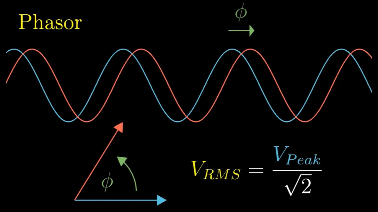
- Resource: by Charles Clayton
- Watch: 00:00 to 00:42
As the video explains, we can define a more general version of Ohm's Law for the phasor domain:
Here, Impedance () is defined as the ratio of the voltage phasor to the current phasor in a circuit element.
Because and are complex numbers, impedance is also a complex number. It tells us two crucial things:
- Magnitude (|Z|): The ratio of the voltage amplitude to the current amplitude ().
- Angle (): The phase difference between the voltage and the current.
In its rectangular form, impedance is written as:
Where:
- is the Resistance, the real part of impedance. It represents energy dissipation (usually as heat).
- is the Reactance, the imaginary part of impedance. It represents energy storage in electric or magnetic fields.
Let's derive the specific impedance expressions for our three passive components.
2. Deriving the Impedance of R, L, and C
Using the phasor relationships we established in the last lesson, we can now find the impedance for each component.
Resistor ()
A resistor's voltage-current relationship is defined by Ohm's Law in the time domain:
When we convert this to the phasor domain, the relationship holds directly for the phasors and :
From the definition of impedance, , we find:
The impedance of a resistor is a purely real number equal to its resistance. Its phase angle is 0°, which confirms that for a resistor, voltage and current are always in phase.
Inductor ()
An inductor's time-domain relationship is:
In our last lesson, we established that the differentiation operator becomes multiplication by in the phasor domain. Applying this transformation, we get:
Solving for the impedance, , we get:
The impedance of an inductor is purely imaginary and positive.
- Magnitude: . The opposition to current flow increases linearly with frequency.
- Angle: . The term signifies a +90° phase shift. This means the voltage across an inductor leads the current through it by 90°.
Capacitor ()
A capacitor's time-domain relationship is:
Transforming this to the phasor domain gives:
This time, we solve for :
To make this easier to interpret, we can multiply the numerator and denominator by :
The impedance of a capacitor is purely imaginary and negative.
- Magnitude: . The opposition to current flow is inversely proportional to frequency.
- Angle: . The term signifies a -90° phase shift. This means the voltage across a capacitor lags the current through it by 90°.
This next video segment provides an excellent summary of these concepts, focusing on the distinction between resistance and reactance and the physical meaning of leading and lagging phases.
- Resource: by Charles Clayton
- Watch: 01:06 to 03:29
3. Resistance vs. Reactance: A Summary
Let's consolidate what we've learned. Impedance has a real part, resistance , and an imaginary part, reactance .
| Component | Time-Domain I-V | Impedance () | Reactance () | Phase Shift (V vs. I) |
|---|---|---|---|---|
| Resistor | 0° (In Phase) | |||
| Inductor | +90° (V leads I) | |||
| Capacitor | -90° (V lags I) |
A key insight here is the frequency dependence of reactance:
- At DC (), an inductor's impedance is (a short circuit), and a capacitor's impedance is (an open circuit). This matches their behavior in DC circuits.
- At very high frequencies (), an inductor's impedance (an open circuit), and a capacitor's impedance (a short circuit). This behavior is fundamental to how filters work, which we will study shortly.
4. Impedance in Action: The Voltage Divider
The true beauty of impedance is that it allows us to analyze AC circuits using the same algebraic techniques we used for DC circuits. The only difference is that we are now manipulating complex numbers.
Let's watch the final segment of the Zach Star video, which brilliantly demonstrates this by solving for the voltage across a capacitor in an RC circuit.
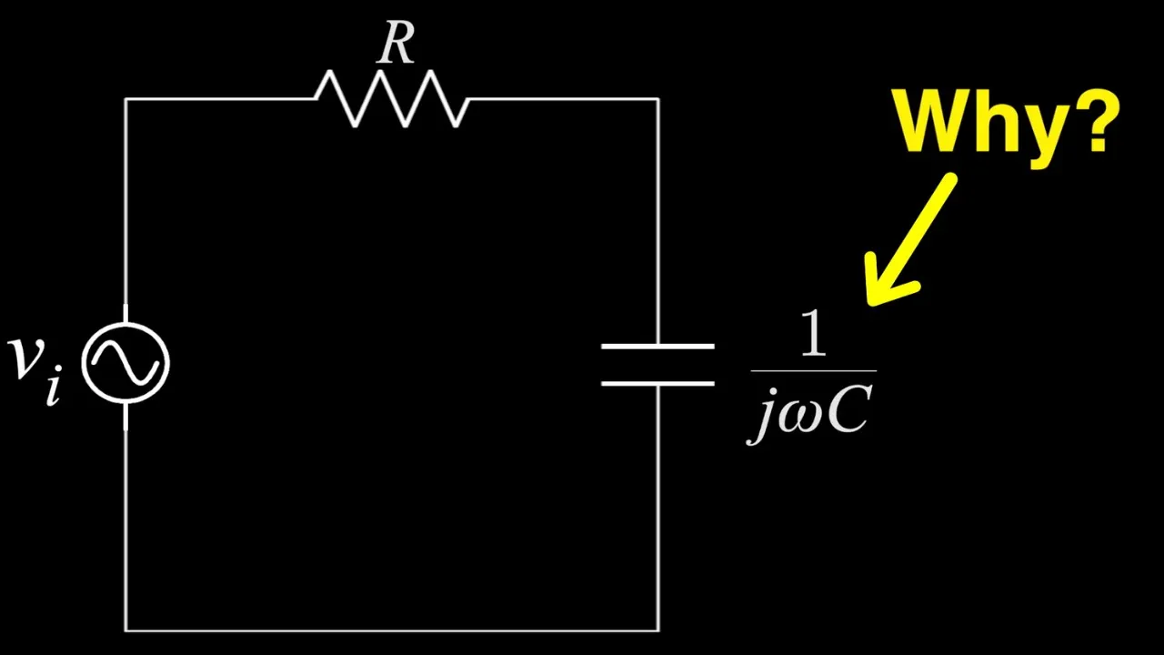
- Resource: by Zach Star
- Watch: 07:46 to 11:30
As the video shows, a problem that would require solving a first-order differential equation in the time domain becomes a simple algebraic voltage divider in the frequency domain:
This powerful simplification is the entire reason we use phasors and complex impedance. It's the core technique you'll use for AC circuit analysis from here on out.
Conclusion
Congratulations! You have now mastered one of the most essential concepts in radioelectronics. By defining impedance, we have unified the behavior of resistors, inductors, and capacitors into a single, elegant framework.
Key Takeaways:
- Impedance () is the frequency-domain equivalent of resistance, defined as .
- Impedance is a complex number , where is resistance and is reactance.
- The impedance of a resistor is .
- The impedance of an inductor is , causing voltage to lead current by 90°.
- The impedance of a capacitor is , causing voltage to lag current by 90°.
- Impedance allows us to use DC circuit analysis techniques (Ohm's Law, KVL, KCL, voltage dividers) for AC circuits, by simply using complex algebra.
What's Next?
In the next lesson, "AC Circuit Analysis using KVL, KCL, and Complex Impedance," we will put this new tool to work. You will learn how to combine impedances in series and parallel and apply Kirchhoff's laws in the frequency domain to solve for currents and voltages in more complex AC circuits.