
Welcome back. In the previous lesson, you used KCL and KVL to solve circuits systematically. Those same laws remain underneath today’s topic, but Thévenin and Norton equivalents give you a more efficient viewpoint: rather than re-solving an entire source network every time a load changes, you replace the network by a two-element model as viewed from one selected pair of terminals.
This is especially useful in analog design. A bias network, an amplifier output, or a current mirror can often be treated as a source with a finite output resistance. For now, we will establish the resistor-and-independent-source version carefully; later, the same idea will reappear in MOS small-signal circuits.
By the end of this lesson, you should be able to find the Thévenin or Norton equivalent at a port and use it to predict load voltage, current, and power.
A two-terminal network viewed from its port
A port is a pair of terminals through which one circuit connects to another. Label the terminals and . Everything on one side of that boundary is the source network; the component or circuit attached across and is the load.
For any linear resistive network containing independent sources, the source network can be replaced, as seen from its port, by either of two equivalent forms:
- Thévenin equivalent: an ideal voltage source in series with a resistance .
- Norton equivalent: an ideal current source in parallel with a resistance .
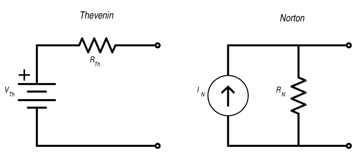
“Equivalent” has a precise meaning: any load connected to the port has the same terminal voltage and current whether it is connected to the original network or to its equivalent model. The internal currents of the original circuit may be very different, but the load cannot detect that difference.
The Thévenin form is usually most convenient when the load is naturally in series with the source resistance. The Norton form is convenient when the load appears as a parallel branch or when the required result is a current.
The two quantities that define a Thévenin equivalent
A Thévenin equivalent is fully specified by:
and
Thévenin voltage: the open-circuit port voltage
Remove the load while leaving the rest of the circuit unchanged. The voltage across the now-open terminals is the Thévenin voltage:
where is the open-circuit voltage.
An open circuit means that no current can leave the source network through the load terminals. It does not mean every resistor in the original network has zero current. Only the branch that has been opened is guaranteed to carry zero current.
Thévenin resistance: resistance seen looking into the port
To find in a circuit containing only independent sources:
- Remove the load.
- Set every independent voltage source to zero volts, replacing it with a short circuit.
- Set every independent current source to zero amperes, replacing it with an open circuit.
- Calculate the equivalent resistance seen from the port.
The replacements follow directly from ideal-source definitions:
- An ideal voltage source constrained to behaves as a wire.
- An ideal current source constrained to supplies no current, so it behaves as an open branch.
A common mistake is to deactivate sources while finding . Do not do that. All original sources must remain active when calculating the open-circuit voltage. Source deactivation is only for finding the resistance seen at the port.
How to Use Thevenin's Theorem | DC Network Analysis
Read the Thévenin procedure in All About Circuits. It reinforces the distinction between finding the open-circuit voltage and finding the resistance seen by the load.
In the section “Calculate Thevenin Equivalent Circuits—Thevenin Voltage and Thevenin Resistance,” follow the open-circuit-voltage procedure. Then continue from “To find the Thevenin series resistance for our equivalent circuit” through the source-deactivation procedure. Finally, in “Applying the Thevenin Equivalent Circuit,” read the load calculation. Focus on what is removed, what remains active, and why the final model can be reused for a different load.
A complete Thévenin calculation
Consider a circuit whose output port consists of node and ground :
- an ideal source establishes a node relative to ground;
- a resistor connects that node to terminal ;
- a resistor connects terminal to ground;
- a load resistor will later connect from to ground.
The source network is the source plus the and resistors. The chosen load is external to it.
Step 1: Find the open-circuit voltage
First remove . The and resistors form a voltage divider between and ground:
Thus, terminal is at relative to terminal when no load is present.
Step 2: Find the resistance seen from the port
Now set the independent source to zero. Replacing it with a short circuit makes the left side of the resistor ground.
From terminals and , both resistors now connect directly to ground, so they are in parallel:
The entire original network can therefore be replaced by a Thévenin source of in series with .
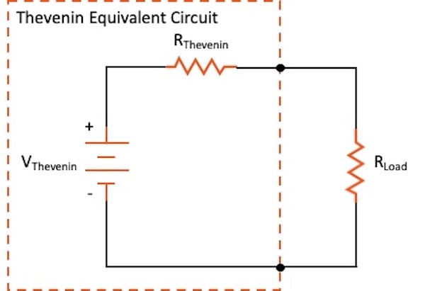
Step 3: Attach a load and calculate its behavior
Suppose that
The load current is now found from one series-loop equation:
The load voltage is:
Equivalently, use the voltage-divider form:
The load power is:
The benefit becomes clear when changes. You do not need to reanalyze the original divider network. Keep and , substitute the new , and calculate again.
Direct-circuit verification
A good engineering habit is to verify one result in the original circuit. With the load attached, the lower part of the original circuit has:
The output voltage of the original circuit is therefore:
This equals the Thévenin-model load voltage, as it must.
Norton form and source transformation
The Norton equivalent represents the same port with a current source in parallel with a resistance .
The two forms are related by:
For the example circuit:
Thus, its Norton model is:
- a current source,
- in parallel with .
If the Norton current-source arrow is drawn from terminal toward terminal , it supplies current upward into the output node. A short placed across the port carries from to . Therefore:
where is the short-circuit current delivered by the network.
With the load reconnected, the Norton current divides between and . The load current is:
This matches the Thévenin result exactly.
Thevenin's Theorem - Circuit Analysis
Watch The Organic Chemistry Tutor’s “Thevenin’s Theorem - Circuit Analysis” for a full worked circuit containing both a voltage source and a current source. It demonstrates the practical bookkeeping behind the method.
Watch the goal for the structure of a Thévenin replacement. Then study finding resistance, especially the replacement of voltage sources by shorts and current sources by opens. Continue with finding voltage to see how an open circuit affects branch current, and finish with the load check to connect the equivalent back to a real load.
Choosing a method for
For networks with only independent sources, source deactivation is usually fastest. But two other methods are important.
Open-circuit and short-circuit method
If you can find both the port’s open-circuit voltage and short-circuit current, then:
Use a consistent current direction: here, is taken as the current supplied from terminal through the external short to terminal .
This method is often convenient if a short circuit simplifies the network. In other cases, a short could create a very large current, so it may be safer or simpler to use source deactivation.
Networks with dependent sources
A dependent source is controlled by a voltage or current somewhere else in the circuit. Later MOS small-signal models will contain dependent current sources such as , so this case matters.
When finding :
- deactivate independent sources only;
- keep all dependent sources active;
- apply a test voltage across the port;
- calculate the resulting test current entering the network;
- compute:
The reason is physical: a dependent source is part of the device behavior of the network. Turning it off would alter the network you are trying to model.
For the nonlinear large-signal behavior of a MOSFET, a single Thévenin resistance generally does not describe every operating point. But after you linearize around a DC bias point, the small-signal MOS circuit is linear, and Thévenin/Norton reasoning becomes directly applicable.
What source and load resistance tell you
The ratio of load resistance to equivalent resistance determines whether a source behaves approximately like an ideal voltage source or ideal current source.
For a Thévenin source:
If
then:
The load barely changes the output voltage. This is the desired condition for a voltage amplifier driving a high-resistance load: low output resistance and relatively high load resistance.
For a Norton source, the load current is:
If
then:
The source behaves approximately like an ideal current source. This is the desired condition for a MOS current mirror or current-bias branch: high output resistance relative to the load’s effective resistance.
There is also a classical power-transfer result. A resistive load receives maximum power from a Thévenin source when:
At that point, the load voltage is half the open-circuit voltage:
However, the efficiency is only , because the same power is dissipated in . This condition is useful for matching and power-transfer reasoning, but it is usually not the desired operating point for low-power integrated voltage amplifiers, which typically want much less loading.
A reliable exam and design workflow
When asked for the equivalent seen by a load, use this sequence:
- Identify the port and clearly mark the load terminals.
- Remove the load without changing the source network.
- Find as the voltage across the open port.
- Find by deactivating independent sources and reducing the resistance seen into the port.
- Draw the Thévenin model and reconnect the load.
- Use the series circuit to calculate , , and .
- If Norton form is useful, convert using:
- Check limiting cases:
- If becomes very large, then should approach .
- If becomes very small, then should approach zero and the load current should approach .
Key takeaways
A linear source network connected to a two-terminal port can be replaced by either:
or:
The defining relationships are:
When finding , short independent voltage sources and open independent current sources. Keep dependent sources active and use a test source when they are present.
Next, you will move from static resistor networks to capacitors and first-order RC circuits. The port-resistance idea developed here will become the resistance seen by a capacitor, which determines the circuit time constant and transient response.
Can't find a good explanation? Sign up and we'll make it for you
Sign up