
Welcome back. In the previous lesson, you established the voltage convention , and learned why and are the key NMOS variables, while and are often clearer for PMOS. We now use those voltages to make the first essential MOSFET decision: is the transistor off, operating as a voltage-controlled resistor, or operating as an approximate current source?
By the end of this lesson, you will be able to determine cutoff, triode (also called linear or ohmic), and saturation from terminal voltages for both NMOS and PMOS transistors. This classification must be done before choosing a drain-current equation, checking amplifier voltage swing, or interpreting a Cadence operating point.
The physical idea: form a channel first
Consider an NMOS with its source at a lower potential than its drain. A sufficiently positive gate-to-source voltage attracts electrons beneath the oxide and creates an n-type inversion layer connecting source and drain. The minimum voltage needed to form a useful channel is the threshold voltage .
For a first-pass long-channel model:
- If is below threshold, there is no strong inversion channel.
- If exceeds threshold, a channel exists.
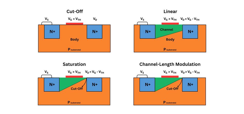
- Once a channel exists, decides whether the channel reaches all the way to the drain or pinches off near the drain.
The quantity that measures how strongly the channel has been created is the overdrive voltage:
For an NMOS to be on in the usual strong-inversion model, must be positive.
Do not confuse threshold voltage with a fixed universal value such as . It depends on process, device dimensions, temperature, and body bias. In a circuit problem, use the value given. Later, you will see how a source-to-body voltage changes the effective threshold through body effect.
NMOS: channel continuity decides triode versus saturation
For an NMOS, the gate voltage relative to the source is . At the drain end of the channel, however, the relevant quantity is gate voltage relative to the drain:
Using the source-referenced variables from the previous lesson:
This identity gives a direct physical test.
If the gate-to-drain voltage remains above threshold,
then inversion exists even at the drain end. The channel is continuous from source to drain, and the NMOS is in triode.
If increasing makes the gate-to-drain voltage fall to threshold,
the channel just reaches pinch-off at the drain end. Substituting gives:
This is the boundary between triode and saturation.
If rises beyond this value, the channel is pinched off near the drain and the NMOS is in saturation:
Pinch-off does not mean that drain current stops. Electrons still travel from the source through the channel and are swept through the high-field depletion region to the drain. Instead, in the ideal long-channel model, increasing further has little effect on current. That approximate current-source behavior is why analog amplifiers usually bias their transistors in saturation.
NMOS Transistor - Regions of Operation - Cut - Off, Linear, Saturation | Know - How
Watch “NMOS Transistor - Regions of Operation - Cut - Off, Linear, Saturation” by Electronics Insight for a visual account of channel formation, tapering, and pinch-off.
Begin with cutoff to connect the absence of a channel with an off transistor. Then watch the linear region, focusing on why a channel exists across the whole source-to-drain distance but narrows near the drain. Finish with saturation and the summary. Keep the boundary V_{DS}=V_{GS}-V_{TN} in view throughout.
The NMOS decision table
Assume the intended NMOS orientation: source is the lower-potential terminal, drain is at the same or a higher potential, and the body junctions remain reverse biased.
| Region | Voltage conditions | Physical interpretation |
|---|---|---|
| Cutoff | No strong-inversion channel; is approximated as zero. | |
| Triode / linear / ohmic | and | A continuous channel joins source and drain; the device behaves approximately as a gate-controlled resistance. |
| Saturation | and | The channel pinches off at the drain end; the device behaves approximately as a gate-controlled current source. |
The same triode-versus-saturation test can be stated with :
This version is especially useful when the gate and drain voltages are immediately visible in a schematic.
The equality case
At the exact condition
the device is at the boundary between triode and saturation. In hand analysis, it is usually acceptable to call this the saturation boundary. In a simulator, the displayed region label can depend on the compact model and its internal tolerances. The important fact is that there is zero saturation margin: a small output-voltage change can move the transistor into triode.
PMOS: use positive source-referenced quantities
For a PMOS in normal operation, the source is at the higher voltage. The PMOS threshold is negative:
You could use and , which will normally be negative. For practical hand analysis, it is much cleaner to use positive PMOS voltage magnitudes:
Define a positive PMOS overdrive:
The PMOS region tests have exactly the same structure as the NMOS tests:
| Region | PMOS condition |
|---|---|
| Cutoff | |
| Triode | and |
| Saturation | and |
For PMOS, saturation can also be recognized from the gate-to-drain voltage. A PMOS is saturated when the gate is not sufficiently below the drain to sustain inversion at the drain end.
The symmetry is worth remembering:
- NMOS: compare with .
- PMOS: compare with .
The sign conventions differ, but the physical story is the same: gate voltage establishes the channel; drain-to-source voltage determines whether the channel remains continuous at the drain end.
Worked classifications from terminal voltages
Example 1: NMOS in cutoff
Suppose:
First calculate the controlling gate-source voltage:
Since
the transistor is in cutoff.
Notice that is high, so is high as well. That does not turn the device on. A drain voltage cannot create the inversion channel that the gate has failed to create.
Example 2: NMOS in triode
Now let:
Calculate the gate-source voltage and overdrive:
Then calculate the drain-source voltage:
The device is on because , and:
Therefore, the NMOS is in triode.
You can confirm this with the gate-to-drain form:
Since
the channel persists at the drain end, which is exactly the triode condition.
Example 3: NMOS in saturation
Keep the same gate and source voltages, but raise the drain voltage:
The overdrive remains:
But now:
Since
the NMOS is in saturation.
Equivalently:
Since
the drain end cannot remain inverted. The channel pinches off near the drain.
Example 4: PMOS classification
Consider a PMOS with:
Use positive PMOS source-referenced quantities:
The PMOS is on because:
And since:
it is in saturation.
If the drain instead rose to , then:
Because , the same PMOS would be in triode.
This is an important amplifier-design point: for a PMOS current-source load near , allowing its drain voltage to rise too close to its source can push it out of saturation.
A reliable classification workflow
For every MOSFET in a DC circuit, use the same sequence.
-
Identify the device type and intended source.
For a normally connected NMOS, the source is the lower-voltage terminal. For a normally connected PMOS, it is the higher-voltage terminal. -
Calculate source-referenced terminal voltages.
Use and for NMOS; use and for PMOS. -
Check whether the transistor is on.
Compare with , or with . -
Calculate overdrive only if the transistor is on.
-
Compare drain-source voltage with overdrive.
A smaller drain-source voltage gives triode operation; a sufficiently large drain-source voltage gives saturation. -
Check the physical assumptions.
The usual three-region rules assume the body-source and body-drain junctions are not forward biased and that source and drain have their intended roles.
If circuit node voltages are not known initially because they depend on , the procedure is slightly different: assume a region, solve the circuit using that region’s current equation, then verify the region inequalities. The next lesson will develop the drain-current equations needed for that process.
Two practical cautions
Saturation is not the same as “fully on”
In digital-switch language, a low-resistance MOSFET is often described as “on.” For analog design, that wording can be misleading:
- Triode means the MOSFET is acting relatively resistive.
- Saturation means the MOSFET is acting more like a controlled current source.
Most common-source amplifiers, differential pairs, current mirrors, and cascode stages require selected transistors to remain in saturation over their intended signal swing.
Saturation current is not perfectly constant
The ideal long-channel model says that saturation current is independent of . Real MOSFETs exhibit channel-length modulation: as increases, the pinch-off region extends and the effective channel becomes slightly shorter. The drain current then increases somewhat with .
Channel-length modulation is not a separate basic operating region. The device is still in saturation when:
Later, this non-ideal slope will become the finite output resistance , which limits amplifier gain.
For a brief Cadence-oriented observation, set an NMOS gate voltage to a value above threshold, keep the source and body at ground, and run a DC sweep of . The transition near
is the triode-to-saturation boundary. Past that point, a real-device curve will usually retain a small upward slope rather than becoming perfectly flat.
Key takeaways
A MOSFET operating region is determined by its terminal voltages and threshold voltage.
For an NMOS:
For a PMOS, use , , and the positive threshold magnitude . The structure of the test is identical.
The most useful physical interpretation is this: triode means the inversion channel reaches from source to drain; saturation means the channel pinches off at the drain end but current continues to flow. In the next lesson, you will turn these region conditions into quantitative long-channel NMOS and PMOS drain-current equations, including channel-length modulation.
Can't find a good explanation? Sign up and we'll make it for you
Sign up