
Welcome back. Previously, you learned to classify a MOSFET as cutoff, triode, or saturation from its terminal voltages. That classification now becomes quantitative: each region has a drain-current equation. These equations are the starting point for finding DC bias points, choosing transistor dimensions, and eventually designing amplifier stages.
In this lesson, you will calculate long-channel NMOS and PMOS drain current from , , terminal voltages, and process parameters. You will also include channel-length modulation, the real-device effect that prevents a saturated MOSFET from being a perfectly constant current source.
From a formed channel to a current equation
The long-channel MOSFET model assumes strong inversion, a sufficiently long channel, and no body effect unless an effective threshold voltage is already supplied. For now, treat or as known constants.
For an NMOS, define the overdrive voltage:
A positive means that an inversion channel exists. Along that channel, however, voltage rises from the source toward the drain. Therefore, the gate-to-channel voltage is strongest at the source and weakest near the drain. The channel becomes progressively thinner as increases.
The gradual-channel model represents this by integrating the channel conductance from source to drain. The result is the familiar triode-region equation. You do not need to reproduce its full derivation from memory for most circuit problems, but you should understand why the result contains both a term proportional to and a term proportional to .
Gradual Channel Approximation in MOSFET | Drain Current Equation of MOSFET | MOSFET Characteristics
Watch “Gradual Channel Approximation in MOSFET | Drain Current Equation of MOSFET | MOSFET Characteristics” from Engineering Funda. It derives the long-channel current expressions from the channel charge and then connects the triode result to saturation.
Watch the triode derivation, focusing on why the channel depth varies along its length and how integration produces the current equation. Then watch the saturation result, where the triode expression is evaluated at pinch-off. Do not worry about memorizing every derivation step; focus on the physical meaning of W, L, overdrive, and the saturation boundary.
Two process-and-geometry quantities appear repeatedly:
where:
- is electron mobility.
- is gate-oxide capacitance per unit area.
- is the NMOS process transconductance parameter, usually expressed in .
- is channel width and is channel length.
- is the device transconductance parameter.
Because is dimensionless, you may use micrometres for both and , provided they use the same unit.
A wider transistor has more parallel current paths and carries more current. A longer transistor has a more resistive channel and carries less current. Thus, for unchanged terminal voltages,
Different textbooks use slightly different notation. Some call simply , while others use . Before substituting numbers, always establish whether the stated parameter already includes .
The long-channel NMOS current equations
Using the conventional NMOS drain current , positive from drain to source, the three-region model is as follows.
| Region | Conditions | Long-channel current |
|---|---|---|
| Cutoff | ||
| Triode | , | |
| Saturation, ideal | , |
The triode expression can also be written directly in terms of :
The ideal saturation equation is:
At the boundary , both equations give the same result:
This agreement is useful for checking that the equations are physically consistent.
Read K. Webb’s treatment of the triode and saturation current equations. It gives a compact explanation of channel tapering, pinch-off, and the dependence of drain current on transistor dimensions.
In the “Triode Region - i-v Relationship” section on pages 15–16, read the triode equation and identify the meaning of each term in k_n'W/L. Then move to “Device Operation – Channel Pinch-Off” and “Saturation - i-v Relationship” on pages 18–21. Read the pinch-off setup, then continue through the saturation-current derivation. Focus on why the effective voltage across the channel becomes V_{OV} after pinch-off.
The low- limit
When is much smaller than , the quadratic term is relatively small:
Then:
This has the form of Ohm’s law, so the MOSFET behaves approximately as a resistor:
This approximation is useful for MOS switches, but analog amplifiers normally aim to keep their signal transistors in saturation instead.
PMOS equations: use positive voltage and current magnitudes
A PMOS has a negative threshold voltage:
Although you can write PMOS equations using negative , , and , that approach often creates avoidable sign errors. For hand analysis, use the positive source-referenced quantities:
Define as the positive current magnitude flowing from source to drain. Then the PMOS equations have exactly the same form as the NMOS equations:
| Region | Conditions | PMOS current magnitude |
|---|---|---|
| Cutoff | ||
| Triode | , | |
| Saturation, ideal | , |
where:
For a PMOS, is lower than , so is usually smaller than . In practical CMOS design, a PMOS is often made wider than an NMOS to obtain comparable current drive.
If a problem explicitly requests the conventional terminal current , defined as positive entering the drain, then normal PMOS operation gives:
State your convention clearly. In analog design calculations, reporting the positive magnitude is usually clearest.
Channel-length modulation: saturation current is not perfectly constant
The ideal saturation equation predicts a flat -versus- curve. A real MOSFET does not behave that way.
After pinch-off, increasing expands the drain depletion region. This moves the pinch-off point slightly toward the source and reduces the effective channel length. Since drain current is inversely related to channel length, the drain current rises with .

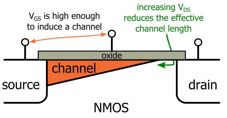
The standard first-order hand-calculation model modifies the saturation equation:
Here, is the channel-length modulation parameter, with units of .
For PMOS, using positive magnitudes:
The parameter is generally larger for shorter channel lengths. Therefore, short-channel devices exhibit a stronger dependence of saturation current on output voltage. This is one reason that increasing can improve analog gain, although it also costs area and capacitance.
The modulation equation belongs to saturation analysis. Do not automatically attach the factor to the basic long-channel triode equation unless a particular model or problem explicitly instructs you to do so.
Read the channel-length modulation discussion in K. Webb’s notes to connect the nonzero saturation slope to a physical shortening of the channel.
In the “Channel-Length Modulation” material on pages 43–46, begin with the ideal-saturation premise. Continue through the explanation that the drain depletion region grows and the effective channel becomes shorter. Finish with the lambda model. Focus on the fact that \lambda captures a real output-voltage dependence, rather than defining a new operating region.
A convenient way to separate the ideal current from the modulation correction is:
Thus, if two saturated operating points have the same but different , their current ratio is:
Later, the same effect will produce the finite small-signal output resistance , which strongly limits the gain of a common-source amplifier.
A reliable current-calculation workflow
For every transistor, use the following sequence:
-
Calculate the source-referenced voltages.
NMOS uses and . PMOS uses and . -
Check whether the device is on.
Compare with for NMOS, or with for PMOS. -
Calculate overdrive.
Use for NMOS and for PMOS. -
Determine the operating region.
Compare the applicable drain-to-source voltage with overdrive. -
Form .
Multiply the process parameter by . -
Use the equation for the verified region.
In saturation, include channel-length modulation if is given or requested. -
Check units and physical plausibility.
With in , current must come out in amperes.
When circuit voltages depend on the unknown drain current, assume a plausible region, solve using its equation, then verify the region conditions using the resulting node voltages. The next module will use this exact approach for complete biased amplifier stages.
Worked examples
NMOS in triode
Given:
First calculate the overdrive and device parameter:
Since:
the transistor is in triode. Therefore:
The result is below the ideal saturation current for the same , as expected, because has not yet reached the saturation boundary.
NMOS in saturation with channel-length modulation
Given:
The overdrive and device parameter are:
The region check is:
Thus the device is saturated. The ideal saturation current is:
Now apply channel-length modulation:
Channel-length modulation increases the current by about , or , relative to the ideal model.
PMOS in saturation with channel-length modulation
Given:
Use the positive PMOS variables:
Because:
the PMOS is in saturation. Its current magnitude is:
Thus the conventional PMOS drain current, if defined as positive entering the drain, is:
A short Cadence observation
In Cadence, build a simple NMOS testbench with source and bulk connected to ground. Set to a constant value above threshold, then perform a DC sweep of the drain voltage from to .
Use a sufficiently wide device and inspect the plot of versus :
- At low , the curve should rise strongly and nonlinearly: triode operation.
- Near , the curve bends toward saturation.
- Beyond that point, a real PDK model will show a nonzero slope due to channel-length modulation and other short-channel effects.
Repeat the sweep with a longer . The long-channel equations predict a smaller , and the saturated curves should generally become flatter. Exact numerical agreement is not expected: Cadence compact models include effects beyond this first-order long-channel model.
Key takeaways
The long-channel drain-current equations connect transistor dimensions and terminal voltages to DC current.
For NMOS:
in triode, and:
in saturation when channel-length modulation is included.
For PMOS, use positive quantities , , , and . The equations have the same form, with PMOS parameters.
The most important habit is to determine the operating region before using an equation, and to verify that region after solving a circuit. Next, you will use these equations inside complete biased MOS stages to calculate DC operating points, voltage headroom, and saturation margins.
Can't find a good explanation? Sign up and we'll make it for you
Sign up