
Hello! Welcome to your next lesson on fluid mechanics.
In our last session, we focused on calculating major head loss (), the energy lost due to friction along straight sections of pipe. We used the Darcy-Weisbach equation and the Moody chart to quantify this loss, adding it to the Bernoulli equation to create a more realistic model of fluid flow:
Today, we'll complete this picture by accounting for the other type of energy loss: minor losses. These occur when the fluid passes through components like valves, bends, and tees. While the name "minor" might suggest they are insignificant, in many real-world systems—especially compact, complex ones like aircraft hydraulic and fuel systems—these losses can be as large or even larger than the major losses.
Your learning outcome for this lesson is to account for minor losses in pipe systems from fittings, bends, and valves using loss coefficients. By the end, you will be able to calculate the total head loss for a complete piping system.
1. What Are Minor Losses?
Major losses are distributed over the length of a pipe. Minor losses, in contrast, are localized pressure drops that occur when a component disrupts the smooth flow of the fluid. This disruption creates turbulence and eddies, which dissipate energy.
To get a clear picture of what causes these losses, please watch the beginning of the following video.
Fluid Mechanics: Topic 8.7 - Minor losses in pipe systems
This video from CPPMechEngTutorials introduces the concept of minor losses, explains why they occur, and shows the common components that cause them.
Watch the first two segments of the video (from 0:00 to 1:40). Pay attention to: The distinction between major and minor losses. The physical reason for minor losses (flow separation and eddies). The list of common components that cause these losses.
As the video explained, any component that forces the fluid to change direction, speed, or flow pattern will introduce a minor loss. This includes:
- Pipe entrances and exits
- Sudden or gradual expansions and contractions
- Bends, elbows, and tees
- Valves, filters, and flow meters
2. The Loss Coefficient Method (K-Factor)
Calculating the complex, turbulent flow through a valve or an elbow from first principles is incredibly difficult. Instead, engineers use a practical, empirical approach centered on the loss coefficient, . The head loss () for a single component is calculated using a formula that should look familiar:
Where:
- is the minor head loss (in meters).
- is the dimensionless loss coefficient (also called resistance coefficient).
- is the average fluid velocity in the pipe associated with the component.
- is the velocity head.
The value of depends on the geometry of the component and is determined experimentally. For common fittings, these values are readily available in tables.
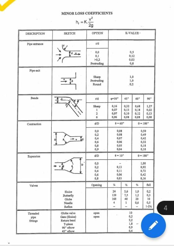
For a system with multiple components, the total minor loss is simply the sum of the individual losses. If the pipe diameter remains constant throughout the system, the velocity is the same for all components, and the equation simplifies nicely:
If is constant:
An Analogy from Electronics
Given your background in electronics, you can think of a piping system as being analogous to an electrical circuit. This analogy is quite powerful for building intuition.
- Pressure Head () is like Voltage (). It's the potential that drives the flow.
- Flow Rate () is like Current (). It's the amount of "stuff" moving through the system.
- Head Loss () is like Resistance (). Both straight pipes (major loss) and fittings (minor loss) "resist" the flow.
Just as a circuit has resistors that cause voltage drops (), a pipe system has friction and fittings that cause head (pressure) drops. Each valve and elbow adds "resistance" to the system, which the pump must overcome. The K-factor is essentially a way to quantify the resistance of each fluid component. This concept is further explored in the handout from Ansys Innovation Space, "Minor Losses in Pipes and Ducts" (LINK).
3. Calculating Total Head Loss: A Comprehensive Example
Now, let's put everything together. We'll analyze a system by calculating both major and minor losses and see how they contribute to the total head loss. The following video provides an excellent, detailed walkthrough of a practical problem.
Fluid Mechanics: Minor Losses in Pipe Flow (18 of 34)
This video, also from CPPMechEngTutorials, works through a complete problem from start to finish. It demonstrates how to combine the major loss calculations from our previous lesson with the minor loss calculations we've just learned.
Please watch the two main example sections of this video (from 38:05 to 58:56). First Example (38:05 - 52:28): Focus on how the total head loss is calculated for water flowing between two reservoirs. Observe the step-by-step process: Writing the energy equation. Calculating major loss (h_L) using the Moody chart (a good refresher!). Identifying all minor loss components (entrance, elbows, valve, exit). Finding the K-value for each component and summing them. Calculating total minor loss (h_m). Adding major and minor losses to find the total elevation difference (H). Second Example (52:28 - 58:56): This part reverses the problem and adds a pump. It shows how to calculate the required pump head (h_p) needed to overcome the exact same total head loss you just calculated. This is a very common and practical engineering task.
This example solidifies the entire process and shows how these calculations are fundamental to system design, such as determining required reservoir heights or sizing a pump.
Test your understanding!
A horizontal pipe system is made of 5 cm diameter commercial steel pipe. It carries water () and consists of the following components:
- A sharp-edged entrance.
- Two standard 90° elbows.
- One fully open gate valve.
- A pipe exit into a large tank.
Using the "Minor Loss Coefficients" table provided in the lesson, calculate the total minor head loss () for this system.
Show answer
First, we need to find the K-factor for each component from the table and sum them up. The pipe diameter is constant, so we can use the simplified formula.
-
Find K-values from the table:
- Sharp-edged entrance:
- Standard 90° elbow: . Since there are two, the total is .
- Fully open gate valve:
- Pipe exit:
-
Sum the K-values:
-
Calculate the velocity head:
-
Calculate the total minor head loss:
The total head loss due to the fittings in this system is approximately 0.97 meters. A pump in this system would need to provide enough energy to overcome this loss, in addition to the major friction loss from the pipe's length.
Conclusion
Today, we've added the final piece to the puzzle of energy loss in pipe flow. By combining major and minor losses, you can now perform a complete analysis of a realistic piping system using the full Extended Bernoulli Equation:
(Where and are head added by pumps or removed by turbines, respectively).
Key Takeaways:
- Minor losses are caused by flow disturbances from components like valves, bends, and area changes.
- They are calculated using the loss coefficient method: .
- The loss coefficient (K) is an empirical, dimensionless value specific to each component's geometry, found in reference tables.
- The total head loss in a system is the sum of all major losses (from pipe friction) and all minor losses (from components).
Next Steps:
So far, we have focused on the energy within the fluid. In the next lesson, we will shift our perspective to analyze the forces that a moving fluid exerts on its surroundings. We will learn to apply the linear momentum equation to calculate these forces, a principle that is fundamental to designing everything from pipe supports and jet engine mounts to understanding the thrust of a rocket.
Can't find a good explanation? Sign up and we'll make it for you
Sign up