
Welcome back. Your IEEE 9-bus case is now structurally complete: buses, lines, GSUs, generators, and loads are present. Before solving it, you need to confirm that every number means what PSS®E thinks it means. A case can converge with an impedance on the wrong base, a line-charging term entered twice, or generation represented with the wrong sign—and still produce misleading results.
This lesson establishes a conversion discipline for published network data. You will distinguish values that must be entered in per unit from those entered directly in MW, Mvar, MVA, kV, or ohms; convert impedances to the correct base; and apply PSS®E’s steady-state sign conventions consistently. This is the same discipline required when moving from a small benchmark to a utility-provided SPP, ERCOT, or WECC study case.
Treat every published number as incomplete until its basis is known
A value such as “” is not usable by itself. It becomes usable only when you know:
- the equipment it describes;
- whether it is in ohms, percent, or per unit;
- its associated MVA base;
- its associated voltage base;
- its electrical location, particularly which side of a transformer it applies to; and
- whether the number is a series impedance, shunt admittance, machine source impedance, or transformer impedance.
This distinction prevents a common error: treating all per-unit quantities as though they belong on the 100 MVA PSS®E system base. They do not.
| Data item | Typical published unit | PSS®E representation and base |
|---|---|---|
| Transmission-line , , total charging | ohms, or p.u. | Normally p.u. on the system MVA base |
| Explicit transformer , | percent or p.u. on transformer rating | Depends on transformer impedance-entry code |
| Generator source impedance | p.u. | Machine MVA base and machine voltage base |
| Generator dispatch and limits | MW, Mvar, MVA | Enter as physical values, not per unit |
| Load demand | MW, Mvar | Enter as physical values, not per unit |
| Branch thermal ratings | MVA | Enter as MVA ratings, usually Rate A/B/C |
| Bus nominal voltage | kV line-to-line | Enter as kV |
| Line charging or fixed shunt | p.u. susceptance | Sign matters; positive is capacitive by IEEE/PSS®E convention |
For each number, create a short audit note before data entry:
Value:       5% transformer impedance
Equipment:   T1 GSU
Published base: 45 MVA, 13.8/69 kV
Target representation: explicit transformer
PSS®E entry basis: 100 MVA system base, CZ = 1
Converted value: j0.1111 p.u.
Source and revision: [document, table, page]
This may seem formal for the 9-bus case, but later, when comparing a submitted project model with a utility model, this audit trail is what lets you identify whether a discrepancy is physical, procedural, or simply a base-conversion error.
The per-unit framework: one power base, voltage bases by zone
Per unit normalizes electrical quantities against selected base values. For a three-phase system using line-to-line voltage and three-phase apparent power,
where is in kV line-to-line, is in MVA three-phase, and is in ohms.
The associated base current is
and physical impedance converts to per unit as
The crucial convention is this:
- Use one system apparent-power base across the complete network.
- Use a different voltage base in each voltage zone.
- Make voltage bases change across transformers in the same ratio as their nominal winding voltages.
For the teaching case, the system base is:
At a 230 kV bus, the impedance base is:
So a hypothetical 230 kV line with physical series impedance
becomes:
That is the value you would enter as the line’s positive-sequence series impedance if the line data were supplied in ohms.
How to Base Change Per Unit and Percent Impedance Part 1 (Electrical Power PE Exam)
Watch “How to Base Change Per Unit and Percent Impedance Part 1” from Electrical PE Review for a compact derivation of the impedance base-change formula. It is useful for avoiding the easily reversed MVA-base ratio.
Watch the derivation, where the presenter derives the general impedance conversion from base impedance. Then watch the shortcut, which explains why only the MVA ratio remains when the old and new voltage bases are equal. Focus on which voltage base is in the numerator before relying on the formula.
The general conversion between two per-unit bases is:
The voltage term is not optional. It becomes one only when the old and new voltage bases are identical, or when both voltage bases change in the same ratio across a transformer.
Converting transformer impedance without losing the voltage context
Transformer impedance is often published as a nameplate percentage, for example 5%. In decimal per-unit form:
That p.u. is meaningful only on the transformer’s nameplate MVA base and rated winding voltages.
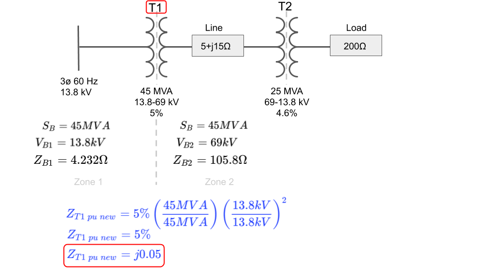
Suppose instead that this transformer is rated 45 MVA, 13.8/69 kV, and has:
Your PSS®E case uses a 100 MVA system base, while its voltage bases remain 13.8 kV and 69 kV in the respective zones. The voltage-base factor is therefore one, so:
The impedance increases on the larger MVA base. This is physically sensible: 100 MVA represents a larger reference current than 45 MVA, so the same physical transformer leakage impedance occupies a larger per-unit fraction of the system base impedance.
Choose the PSS®E transformer entry code before entering the number
The entry field does not determine the physical impedance; it determines how PSS®E interprets what you type.
For an explicit two-winding transformer, the common alternatives are:
| PSS®E impedance convention | Meaning of entered and | What you should enter |
|---|---|---|
CZ = 1 | P.u. on the system MVA base and winding voltage bases | First convert nameplate impedance to the system base |
CZ = 2 | P.u. on transformer winding MVA base and winding voltage bases | Enter nameplate per-unit impedance with the matching winding base |
CZ = 3 | Resistance from load-loss data, reactance in p.u. | Use only when the required nameplate loss data and software convention are understood |
For this IEEE 9-bus teaching case, we are using explicit GSUs with:
- MVA;
- PSS®E transformer impedance convention
CZ = 1; and - winding voltages entered in kV with
CW = 2.
Therefore the GSU reactances you entered in the prior lesson:
are already system-base values. Do not convert them again.
Psse introduction module for power flow study, database preparation and sld making | PDF
Read the Siemens Power Academy slides for the base-impedance formula, the worked conversion examples, and the distinction between explicit and implicit GSU representation.
In the slides on per-unit calculations, begin at the worked prompt the two examples. Follow the 345 kV line conversion and the 500 MVA transformer conversion; note that the voltage term disappears only because the voltage base is unchanged. Then read the slides titled “Machine Data” and “Generator Step-Up Transformer Modeling Options.” Finally, in the transformer-data slide, review the impedance-entry codes, focusing on the distinction between system-base and winding-base entries.
A defensible model records both the published basis and the entered basis. Writing only “” in a calculation sheet is not enough; the sheet should state that it was converted from 5% on 45 MVA to 0.1111 p.u. on 100 MVA.
Branch charging: distinguish total from
Published line diagrams frequently show a nominal- line model with charging split equally between both ends. In that notation, each end has:
PSS®E’s standard branch data uses the total branch charging susceptance, , not the value at one end.
For example, if a published one-line labels:
then the total branch charging to enter in the PSS®E branch record is:
The IEEE 9-bus one-line is a useful reminder: the charging annotations on its transmission paths are labeled . Check the corresponding branch records in your case to ensure you did not enter only half of the published total, or accidentally double a value that was already supplied as total .
The usual PSS®E/IEEE steady-state signs are:
| Element | Positive value means | Typical physical meaning |
|---|---|---|
| Line series | Resistance | Real-power loss |
| Line series | Inductive reactance | Ordinary overhead line or transformer leakage reactance |
| Branch charging | Capacitive susceptance | Charging reactive injection |
| Fixed-shunt | Capacitor | Reactive injection |
| Fixed-shunt negative | Reactor | Reactive absorption |
A line’s series and its shunt charging have different physical meanings and should never be combined into a single “reactance” figure.
Generation, load, and ratings: use physical units, then apply signs consistently
Unlike branch impedance, PSS®E steady-state power quantities are generally entered in physical engineering units.
If a source publishes generation as 0.90 p.u. on a 100 MVA system base, first recover the physical value:
If a project load is given as 0.80 p.u. and 0.30 p.u. on the same 100 MVA base:
Then enter those MW and Mvar values in the appropriate PSS®E load record.
PSS®E steady-state injection convention
A practical rule is:
- Machine records use positive and positive for injection into the network.
- Load records use positive and positive for consumption from the network.
- A positive load is inductive demand.
- A negative load represents capacitive net behavior at that load record.
For the 9-bus teaching case, this gives:
| Bus | Record type | Entered | Entered | Meaning |
|---|---|---|---|---|
| 1 | Machine | MW initially | Mvar initially | Generator injection; swing MW will change after solution |
| 2 | Machine | MW | Initial Mvar | Generator injection |
| 3 | Machine | MW | Initial Mvar | Generator absorbs reactive power initially |
| 5 | Load | MW | Mvar | Inductive demand |
| 6 | Load | MW | Mvar | Inductive demand |
| 8 | Load | MW | Mvar | Inductive demand |
Do not make the sign of a machine’s agree with the sign of a load’s by intuition alone. A generator at Mvar is absorbing reactive power; a load at Mvar is also absorbing reactive power. The records use different reference directions.
Ratings are normally not per-unit values
Transmission and transformer ratings are normally entered as MVA, directly from the applicable rating source:
- Rate A: continuous or normal rating;
- Rate B: emergency rating;
- Rate C: an additional emergency or planning rating, where used.
Do not divide a 300 MVA thermal rating by the 100 MVA system base and enter “3.0” as the branch rating. PSS®E expects 300 MVA.
A branch rating also needs operating context. A conductor may have different normal and emergency ratings by season, ambient condition, or contingency duration. A blank rating in the small teaching case may be acceptable as a documented benchmark limitation; it is not evidence that the branch has unlimited thermal capability.
spp%20model%20development%20procedure%20manual%202022%20v7.0.docx
Read the relevant SPP model-development guidance to connect the 9-bus conversion discipline with production-model expectations for bases, ratings, machine data, and transformer representations.
In the “Line and Transformer Data” discussion, read the branch-base requirement, then continue through the paragraph requiring normal and emergency ratings. In “Generator Data,” read the ZSOURCE guidance. Finally, in the transformer guidance, find the subsection “Transformers” and read the recommendation to set the winding MVA base to the 100 MVA system base. Focus on the distinction between a required data convention and an actual equipment characteristic.
Machine source impedance is the important exception
Machine source impedance, usually entered as , is not a branch impedance. It is on the machine’s own MVA base and machine voltage base.
For example, suppose a synchronous generator has:
If its PSS®E machine record has:
enter:
directly in the machine record. Do not convert it to the 100 MVA case base merely because the network uses a 100 MVA system base.
If you need to express that same physical machine reactance on a 100 MVA base for an external calculation, and the voltage base remains consistent, it becomes:
Both and describe the same physical source impedance. They are just expressed on different bases.
For your current case, all three machines use:
So the stated machine source impedance,
is numerically the same whether viewed on the machine base or the system base. That numerical coincidence is convenient, but do not mistake it for a general rule.
The other essential rule is location: because the three GSUs are explicit transformer records, machine source impedance contains the generator’s electrical source only. It must not contain a second copy of the GSU leakage reactance.
Apply a conversion audit to the IEEE 9-bus case
Before solving, make a compact basis-and-sign register for this specific revision.
| Equipment group | Published or course value | Basis to verify | PSS®E entry treatment |
|---|---|---|---|
| System base | 100 MVA | Case SBASE | Use consistently for network branches and explicit GSUs with CZ = 1 |
| 230 kV lines | Published and p.u. values | Confirm published values are on the selected 100 MVA system base | Enter , , and total |
| GSU 1 | p.u. | Already on 100 MVA system base | Enter directly as explicit transformer impedance |
| GSU 2 | p.u. | Already on 100 MVA system base | Enter directly as explicit transformer impedance |
| GSU 3 | p.u. | Already on 100 MVA system base | Enter directly as explicit transformer impedance |
| Machine sources | p.u. | Machine base is 100 MVA | Enter in machine source fields only |
| Generators | 71.64, 163, 85 MW | Physical power, not p.u. | Positive machine injections |
| Loads | 125, 90, 100 MW | Physical power, not p.u. | Positive load demands |
| Load reactive power | 50, 30, 35 Mvar | Physical reactive demand | Positive inductive load demand |
| Branch ratings | Not source-verified in teaching dataset | MVA and seasonal applicability unknown | Leave provisional values documented; do not claim thermal compliance |
Use this as a pre-solution check:
- Confirm that every branch impedance is stated as either ohms with a known voltage level or p.u. with a known MVA and voltage base.
- Confirm that every transformer has exactly one representation: explicit transformer record or implicit machine-data transformer, never both.
- Confirm that line charging was entered as total , not a single-end value.
- Confirm that generation is positive in machine records and demand is positive in load records.
- Confirm that MW, Mvar, MVA ratings, and kV values have not been divided by the system base before entry.
- Confirm that each blank or zero rating is documented as unknown or unavailable, rather than “unlimited.”
This is also the point to save a traceable revision, such as:
IEEE9_BASECHECK_R00.sav
Add a one-line entry to your manifest:
Basis review: all explicit network impedances confirmed on 100 MVA base;
machine source impedances confirmed on MBASE; line charging entered as total B;
generation/load sign conventions reviewed.
Key takeaways
A reliable PSS®E case requires more than entering correct-looking numbers:
- Per-unit impedance requires known MVA and voltage bases.
- Convert an impedance using:
- Explicit transformer impedances normally use the system base when entered with
CZ = 1; machine source impedances use MBASE. - Generator and load powers are entered in MW and Mvar, not per unit. Positive machine power injects; positive load power consumes.
- PSS®E branch ratings are MVA values, while a branch’s total charging must not be confused with the single-end shown on a nominal- one-line.
- Never duplicate an explicit GSU impedance inside machine data.
Next, you will solve the IEEE 9-bus AC power flow and interpret the resulting mismatch, voltage profile, reactive output, limits, and interchange as engineering checks on this now basis-consistent case.
Can't find a good explanation? Sign up and we'll make it for you
Sign up