
Hello! Welcome to our next lesson.
In our last session, we explored how a conductor moving through a magnetic field experiences an induced voltage, or "motional EMF," described by . We established that the underlying cause is the Lorentz force acting on charges within the conductor.
Today, we will generalize this concept significantly by introducing Faraday's Law of Induction. This powerful law, discovered experimentally by Michael Faraday, provides a complete picture of how EMF is generated. It reveals that any change in the magnetic environment of a circuit—not just motion—will induce a voltage. To quantify this, we first need to define a crucial concept: magnetic flux.
Our goal for this lesson is to state Faraday's law and then apply it to calculate the induced EMF in various scenarios where the magnetic flux is changing.
1. Magnetic Flux ()
Before we can state Faraday's Law, we need a way to measure "how much" magnetic field is passing through a circuit loop. This quantity is called magnetic flux, denoted by .
Conceptually, you can think of it as a count of the number of magnetic field lines piercing a given surface. The more lines passing through, and the more directly they pass through, the greater the flux.
For a uniform magnetic field passing through a flat loop of area , the magnetic flux is defined as:
Where:
- is the magnitude of the magnetic field.
- is the area of the loop.
- is the critical angle between the magnetic field direction and the normal to the loop's surface (a line perpendicular to the plane of the loop).
The SI unit for magnetic flux is the Weber (Wb), where .
For a more formal and detailed definition, including the integral form for non-uniform fields, please read the following section from the MIT course notes.
Chapter 10 Faraday's Law of Induction
These notes from MIT provide a concise and rigorous definition of magnetic flux. Your background in multivariable calculus will make the integral form immediately familiar.
Please read section '10.1.1 Magnetic Flux' (page 10-2). Focus on understanding Equation 10.1.1 and the role of the angle heta.
To complement the text, the following video provides a helpful visual explanation of magnetic flux.
Faraday's & Lenz's Law of Electromagnetic Induction, Induced EMF, Magnetic Flux, Transformers
This video from The Organic Chemistry Tutor clearly explains the concept of magnetic flux and how it depends on the field, area, and angle.
Watch from the beginning to 03:36. Pay close attention to the visual explanation of how the angle heta affects the flux.
2. Faraday's Law of Induction
With magnetic flux defined, we can now state Faraday's discovery in a precise mathematical form.
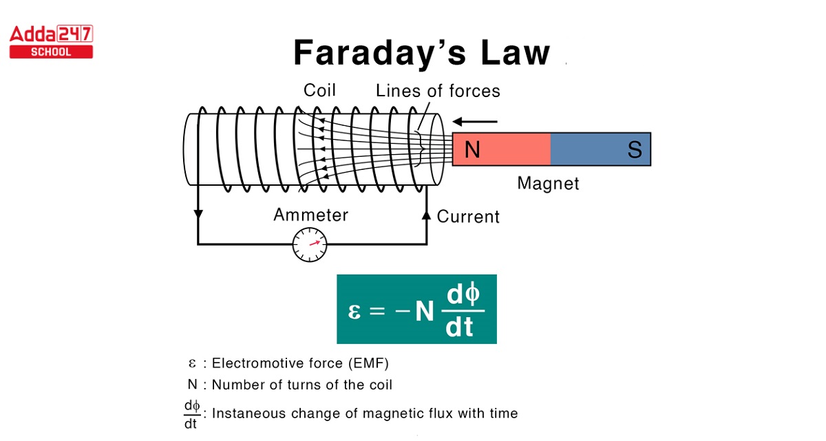
Faraday's Law of Induction states that the induced EMF () in a closed circuit is equal to the negative of the time rate of change of the magnetic flux through that circuit.
For a coil with identical turns, the law is written as:
Let's break this down:
- is the induced EMF (in Volts), which acts like a voltage source in the circuit.
- is the number of turns in the coil. A change in flux has its effect multiplied by the number of loops.
- is the time derivative of the magnetic flux. This is the mathematical core of the law. It's not the flux itself, but its rate of change, that induces the EMF. A stationary magnet inside a coil () induces no voltage. A magnet moving quickly ( is large) induces a large voltage.
The negative sign relates to the direction of the induced EMF and is formally described by Lenz's Law, which we will dedicate our entire next lesson to. For today's calculations, we will focus on the magnitude of the EMF:
Since , we can induce an EMF by changing any of these three factors over time:
- Changing the magnetic field strength .
- Changing the area of the loop.
- Changing the angle between and the loop's normal.
3. Connection to Motional EMF
Faraday's Law is a generalization that must include our previous result for motional EMF, . Let's see how.
Consider the sliding rod from our last lesson. As the rod of length moves at speed , the area of the loop it forms with the rails changes. If it moves a distance in time , the change in area is . The speed is .
Using Faraday's Law (with and ), the magnitude of the EMF is:
Since the magnetic field is constant, we have:
This confirms that motional EMF is simply Faraday's Law applied to a situation where the area is changing.
The following video segment provides an excellent derivation of this connection.
Faraday's & Lenz's Law of Electromagnetic Induction, Induced EMF, Magnetic Flux, Transformers
To see this derivation explained visually, please watch this segment from the video we used earlier.
Watch from 51:56 to 54:33. The instructor derives the motional EMF formula \mathcal{E}=BLV directly from Faraday's Law by considering the rate of change of area.
4. Applying Faraday's Law
The real power of Faraday's Law comes from its ability to handle all scenarios of changing flux. Let's work through some quantitative examples. The MIT notes provide a clear problem-solving framework, which you may find useful to review.
Chapter 10 Faraday's Law of Induction
This section of the MIT notes outlines a 3-step procedure for applying Faraday's Law. It's a useful systematic approach for tackling induction problems.
Read the section '10.8 Problem-Solving Tips: Faraday’s Law and Lenz’s Law' (page 10-16).
Now, let's see this strategy in action.
Example 1: Changing Magnetic Field ()
This is the principle behind electrical transformers. A changing current in one coil creates a time-varying magnetic field, which then induces an EMF in a nearby second coil, even with no motion involved.
Faraday's & Lenz's Law of Electromagnetic Induction, Induced EMF, Magnetic Flux, Transformers
This worked example demonstrates how to calculate the induced EMF in a loop when the magnetic field it's in changes over time.
Watch the example from 35:43 to 40:00. Note how the calculation starts by finding the change in flux, \Delta\Phi_B, and then divides by the time interval, \Delta t, to find the average EMF.
Test your understanding!
A 100-turn circular coil with a radius of 5 cm is in a uniform magnetic field that is perpendicular to the plane of the coil (). The field increases linearly from 0.1 T to 0.9 T in 2 seconds. What is the magnitude of the induced EMF in the coil?
Show answer
- Calculate the area: .
- Calculate the rate of change of the magnetic field:
. - Calculate the rate of change of flux:
Since A and are constant, .
. - Calculate the EMF using Faraday's Law:
.
Example 2: Changing Area ()
As we saw with motional EMF, changing a loop's area in a constant magnetic field induces a voltage.
Faraday's & Lenz's Law of Electromagnetic Induction, Induced EMF, Magnetic Flux, Transformers
Here's an example where the area of a coil is changed by stretching it. This is another direct application of Faraday's Law.
Watch the example from 42:10 to 46:05. This problem also involves an angle, so pay close attention to how the \cos heta term is handled.
Example 3: Changing Angle ()
This is arguably the most important application, as it forms the basis of virtually all commercial electricity generation. By rotating a coil in a constant magnetic field, the angle changes continuously, inducing a continuously varying EMF.
Faraday's & Lenz's Law of Electromagnetic Induction, Induced EMF, Magnetic Flux, Transformers
This final example shows how rotating a coil—and thus changing the angle heta—induces an EMF. This is the fundamental principle of an electric generator.
Watch from 47:50 to 51:56. Notice that the change in flux is calculated as \Delta\Phi_B = BA(\cos heta_f - \cos heta_i).
Conclusion
In this lesson, we have moved beyond the specific case of motional EMF to the general and unifying principle of Faraday's Law of Induction.
Key Takeaways:
- Magnetic Flux () is the measure of the total magnetic field passing through a surface.
- Faraday's Law states that a changing magnetic flux induces an EMF: .
- The magnitude of the induced EMF is proportional to the rate of change of the magnetic flux.
- An EMF can be induced by changing the magnetic field strength (B), the loop area (A), or the angle () between the field and the loop.
Preview of the Next Lesson:
We've successfully used Faraday's law to calculate the magnitude of the induced EMF. However, we've largely ignored the negative sign in the equation. This sign is not arbitrary; it contains crucial physical information about the direction of the induced current. In our next lesson, we will focus entirely on this aspect, which is formalized as Lenz's Law. It answers the question: which way does the induced current flow?
Can't find a good explanation? Sign up and we'll make it for you
Sign up