Hello! Welcome back to our course on Radioelectronics.
In our last lesson, we explored how RC networks can be combined with amplifiers to create oscillators like the RC Phase-Shift and Wien Bridge topologies. We saw that these are excellent for generating sine waves at audio and low frequencies, but their performance diminishes at higher frequencies.
Today, we transition into the realm of radio frequency (RF) electronics by focusing on oscillators that use inductors (L) and capacitors (C). These LC oscillators are the foundational circuits for generating the high-frequency carrier waves used in radio transmitters, receivers, and many other communication systems. This topic should align well with your background in radiophysics.
Our learning outcome is to understand the principles of LC Oscillators, specifically the Colpitts and Hartley topologies, which are workhorses in RF applications. We will examine how they use a resonant LC "tank" circuit to satisfy the Barkhausen criterion for oscillation at much higher frequencies than their RC counterparts.
1. The LC Tank Circuit: The Resonant Heart
Before diving into specific oscillator circuits, we must first understand their core frequency-determining element: the LC resonant circuit, often called a "tank circuit."
While RC circuits create a phase shift that is highly dependent on frequency, an LC circuit exhibits a sharp resonant behavior at a specific frequency. At this frequency, energy is efficiently transferred back and forth between the capacitor's electric field and the inductor's magnetic field. This "sloshing" of energy is the basis for oscillation.
To explore this fundamental concept, please read the following section from an excellent article on LC oscillators.
Inductor/ Capacitor (LC) Oscillators
This first section from the article 'Inductor/ Capacitor (LC) Oscillators' by Elliott Sound Products introduces the LC tank circuit, explains the concepts of series and parallel resonance, and defines the resonant frequency formula.
Please read the text starting from 'When an inductor and capacitor are wired in series or parallel...' down to the end of the section, just before the heading about oscillator requirements. Focus on the difference in impedance for series and parallel resonance and the formula for the resonant frequency.
As you've just read, the LC tank circuit is the key. Here are the main points:
- Resonant Frequency: The natural frequency of oscillation is determined by the inductance (L) and capacitance (C) values:
- Impedance at Resonance:
- A parallel LC circuit has a theoretically infinite impedance at resonance.
- A series LC circuit has a theoretically zero impedance at resonance.
- In oscillators, the tank circuit is typically used in a parallel configuration, presenting a very high impedance load at the resonant frequency and low impedance at all other frequencies.
- The Q Factor: The "Quality Factor" (Q) of the tank circuit is a measure of its efficiency. A high-Q circuit has low losses (i.e., low internal resistance) and a narrow bandwidth. This allows it to act as a highly selective filter, producing a clean sinusoidal output even if the energy is injected into it in short, non-sinusoidal pulses (a common technique known as Class-C operation).
The basic principle of an LC oscillator is to use an amplifier to counteract the energy losses in the tank circuit, providing just enough energy in each cycle to sustain the oscillation. This is another application of the Barkhausen criterion: the amplifier and feedback path must provide a loop gain of 1 and a total phase shift of 0° (or 360°) at the resonant frequency .
2. The Hartley Oscillator: Tapped Inductor Feedback
The Hartley oscillator, invented in 1915, is a classic design distinguished by its use of a tapped inductor to provide the feedback signal.
The tank circuit consists of a capacitor in parallel with a single inductor that has a "tap" or connection point along its winding. This tapped coil acts like an autotransformer. The full winding is part of the resonant circuit, but the feedback signal is taken from the tap.
Let's look at a typical configuration.
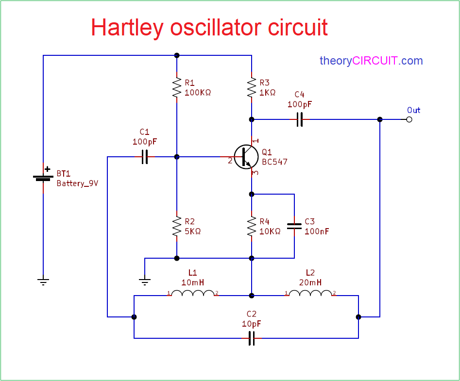
The operation relies on a 180° phase shift provided by the amplifier (a common-emitter BJT is inverting) and another 180° phase shift provided by the tapped inductor. The signal at the top of the inductor (collector side) is 180° out of phase with the signal at the bottom (feedback side) relative to the tap point, which is often connected to ground or a supply rail.
To see the circuit in more detail, please refer back to the Elliott Sound Products article.
Inductor/ Capacitor (LC) Oscillators
This section of the article presents the basic Hartley oscillator circuit and explains how the tapped inductor provides the necessary positive feedback.
Please read the section titled 'Hartley Oscillator' (Figure 3.1). Focus on how the tapped coil inverts the signal to provide positive feedback to the base of the transistor.
The key takeaway for the Hartley oscillator is that the feedback fraction—how much of the output signal is fed back to the input—is determined by the position of the tap on the inductor.
3. The Colpitts Oscillator: Tapped Capacitor Feedback
The Colpitts oscillator, invented in 1918, can be seen as the electrical "dual" of the Hartley. Instead of a tapped inductor, it uses a capacitive voltage divider to provide the feedback signal.
The tank circuit still consists of an inductor and capacitors, but here we use a single inductor in parallel with two capacitors connected in series. The junction between the two capacitors provides the feedback signal.
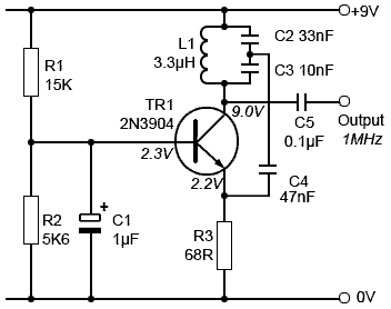
The total capacitance that determines the resonant frequency is the series combination of C2 and C3:
The resonant frequency is then:
The ratio of the capacitances, , determines the feedback fraction. This configuration is often preferred at very high frequencies (VHF) because it can be easier to create a precise capacitive divider than a tapped inductor, and the capacitors can help absorb the transistor's own parasitic capacitances.
Let's look at two resources that explain its operation.
Inductor/ Capacitor (LC) Oscillators
First, read the relevant section from the Elliott Sound Products article, which presents the Colpitts circuit as a direct comparison to the Hartley.
Read the section titled 'Colpitts Oscillator' (Figure 3.2). Note the similarity in structure to the Hartley, but with the inductor replaced by a capacitor divider.
Next, this Wikipedia article provides a clear, step-by-step explanation of the Colpitts working principle, reinforcing how the Barkhausen criterion is met.
Please read the section titled 'Working Principle'. This will give you a concise summary of how the circuit starts up and sustains oscillation.
A notable variation is the Gouriet-Clapp oscillator, which adds a third capacitor in series with the inductor in a Colpitts circuit. This small capacitor dominates the resonance calculation, effectively isolating the tank circuit from the transistor's junction capacitances. This significantly improves frequency stability, a topic we will explore further in our next lesson.
Conclusion
In this lesson, we have made the jump from low-frequency RC oscillators to high-frequency LC oscillators, which are fundamental to radio technology.
Here are the key takeaways:
- LC oscillators use a resonant tank circuit, composed of an inductor and capacitor, as their frequency-determining element. The high Q-factor of the tank circuit ensures a stable frequency and a pure sinusoidal output.
- The Hartley oscillator achieves feedback by using a tapped inductor in its tank circuit.
- The Colpitts oscillator is the dual of the Hartley, using a capacitive voltage divider for feedback.
- Both topologies pair the 180° phase shift from the tank's feedback arrangement with the 180° phase shift of an inverting amplifier (like a common-emitter BJT) to satisfy the Barkhausen criterion.
While LC oscillators are tunable and widely used, their frequency can still drift due to temperature changes and component tolerances. For applications demanding the utmost precision and stability, such as in digital communications or broadcasting frequency standards, an even better solution is needed.
In our next lesson, we will cover "Crystal Oscillators for High-Frequency Stability." These devices replace the LC tank circuit with a quartz crystal that uses a mechanical resonance to achieve a Q-factor thousands of times higher than a standard LC circuit, resulting in exceptional frequency stability.