Hello! Welcome back to our course on Radioelectronics.
In our previous lesson, we investigated LC oscillators like the Hartley and Colpitts topologies. We saw how they use a resonant "tank" circuit to generate high-frequency signals, but we also noted that their frequency stability is limited by component tolerances and temperature drift. For many applications in modern radio and digital systems, a much more precise and stable frequency source is required.
Today, we will explore the component that provides this precision: the quartz crystal. Our learning outcome is to understand Crystal Oscillators for High-Frequency Stability. We will examine the physical principle that makes them work, their electrical model, and the factors that give them a frequency stability orders of magnitude better than LC circuits.
This lesson will connect directly with your radiophysics background by exploring the electromechanical properties of resonators and the engineering trade-offs involved in achieving high stability.
1. The Heart of the Oscillator: The Piezoelectric Resonator
Unlike LC oscillators which store energy in electric and magnetic fields, crystal oscillators rely on a physical phenomenon: piezoelectricity. This is the property of certain materials, most notably quartz (), to generate an electric voltage when subjected to mechanical stress. The inverse is also true: applying a voltage across the crystal causes it to deform mechanically.
A crystal oscillator exploits this effect. A precisely cut slice of quartz crystal is placed between two electrodes. When an AC voltage is applied, the crystal begins to vibrate. Due to its crystalline structure, it has a very stable and well-defined natural frequency of mechanical resonance. The vibrations, in turn, generate a voltage back into the circuit. The result is an electromechanical resonator with exceptional properties.
To analyze its behavior in a circuit, we model the quartz crystal with an equivalent electrical circuit, known as the Butterworth-Van Dyke (BVD) model.
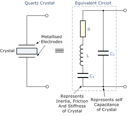
The components of the BVD model are:
- : The motional inductance, representing the crystal's vibrating mass.
- : The motional capacitance, representing the crystal's mechanical stiffness.
- : The series resistance, representing the frictional losses of the mechanical vibration.
- : The shunt capacitance, representing the static capacitance between the electrodes, independent of the crystal's motion.
To understand the mathematical representation of this model, please read the following section from the Wikipedia article on crystal oscillators.
This section provides the mathematical formulation for the crystal's impedance, defining its series and parallel resonant frequencies. This is the foundation for understanding how the crystal behaves in an oscillator circuit.
Please read the section titled 'Electrical model'. Focus on the impedance equation Z(s) and the formulas for the series resonant frequency (ωs) and parallel resonant frequency (ωp).
As you've read, the crystal exhibits two distinct resonant frequencies:
- Series Resonance (): Occurs when the reactance of and cancel out. At this frequency, the impedance is at its minimum, equal only to the low series resistance .
- Parallel Resonance (): Occurs slightly above , where the reactance of the series branch becomes inductive and resonates with the parallel capacitance . At this frequency, the impedance is at its maximum.
The region between and is where the crystal behaves as an inductor. Most common oscillator circuits, like the Pierce oscillator we'll see later, are designed to operate in this region.
2. The Source of Stability: Extremely High Q Factor
The primary reason for the crystal's exceptional frequency stability is its incredibly high Quality Factor (Q). While a well-designed LC tank circuit might have a Q of a few hundred, a quartz crystal can have a Q ranging from 10,000 to over 1,000,000.
This high Q factor arises because the resonator is mechanical, and the internal frictional losses () are extremely low compared to the energy stored in the vibration (, ). A high Q has two critical consequences:
- Extremely Sharp Resonance: The impedance of the crystal changes dramatically with tiny changes in frequency around resonance. This forces the oscillator's feedback loop to lock onto the crystal's natural frequency with very high precision. The crystal acts as a superb filter.
- Low Phase Noise: Phase noise represents small, random fluctuations in the phase of the signal. In an oscillator, this is perceived as frequency instability or "jitter." The high Q of the crystal means it has a very long "memory" of the correct phase, effectively averaging out and suppressing these random fluctuations. This results in a very "clean" signal, which is vital for digital communications and RF systems.
To deepen your understanding of these principles, please read the following material.
This reading covers the fundamental principles of crystal operation and why its high Q factor is so important for stability and low phase noise.
First, read the 'Principle' section for a conceptual overview. Then, jump to the 'Crystal oscillator circuits' section and read from the beginning down to (but not including) the paragraph on 'Spurious frequencies'. Focus on the discussion of positive feedback, the crystal as a filter, the high Q factor, and low phase noise.
3. Factors Affecting Frequency Stability
While a crystal is inherently stable, its frequency is not perfectly constant. Several environmental and physical factors can cause it to drift. Understanding and mitigating these factors is the key to designing high-stability oscillators.
Temperature
Temperature is the most significant factor affecting short-term stability. Changes in temperature alter the crystal's physical dimensions and the elasticity of quartz, causing the resonant frequency to shift.
To combat this, crystals are manufactured with specific crystallographic orientations, or "cuts". The angle of the cut relative to the crystal's axes determines its temperature characteristics.
- AT-cut: This is the most common cut. Its frequency-temperature curve is a cubic parabola, designed to have a "turnover point" (zero slope) near room temperature. This provides excellent stability for typical operating environments.
- SC-cut (Stress-Compensated): This is a more advanced, double-rotated cut used in high-performance oscillators. It has better temperature stability, is less sensitive to mechanical stress, and exhibits lower aging. However, it is more difficult and expensive to manufacture.
Aging
This refers to a slow, long-term, permanent change in frequency over months and years. It is caused by several mechanisms:
- Mass Transfer: Contaminants inside the hermetically sealed package can slowly adsorb onto or desorb from the crystal's surface, changing its mass and thus its frequency.
- Stress Relief: Mechanical stresses from the mounting structure are slowly relieved over time.
- Electrode Changes: The metal electrodes can slowly interact with the quartz.
Other Factors
- Drive Level: Applying too much power to the crystal can cause it to oscillate with excessive amplitude, leading to frequency shifts and even physical damage.
- Mechanical Stress: External vibration and shock can modulate the frequency or cause permanent shifts. SC-cut crystals are specifically designed to minimize this.
The following reading provides more detail on these stability factors.
How Does a Crystal Oscillator Work?
These sections from the Wikipedia article and the Technetron article discuss the various factors that influence a crystal's frequency stability.
Please read the sections 'Frequency Stability and Accuracy' and 'Factors Affecting Frequency Stability and Accuracy'. This provides a good high-level summary.
For a more in-depth look, this section from Wikipedia details the physical mechanisms behind stability issues.
Please read the sections titled 'Stability' and 'Aging'. You don't need to memorize every detail, but focus on understanding the main sources of frequency drift: Q factor, temperature, mechanical stress, and aging mechanisms.
4. Practical Circuits and Stability Enhancement
The most common crystal oscillator circuit is the Pierce oscillator. It uses a single digital logic inverter (like a CMOS NOT gate) or a single transistor as the amplifying element. The crystal, along with two small capacitors, forms a -network feedback path that provides the necessary 180° phase shift to sustain oscillation. Its simplicity, low cost, and reliability make it ubiquitous in digital electronics.
For applications requiring stability beyond what a standard crystal can offer, several enhancement techniques are used:
- TCXO (Temperature-Compensated Crystal Oscillator): Includes a temperature sensor and a voltage-controlled capacitor (varactor) in the circuit. As the temperature changes, the control voltage is adjusted to "pull" the crystal's frequency back to its nominal value, compensating for the thermal drift.
- OCXO (Oven-Controlled Crystal Oscillator): Provides the highest level of stability. The crystal and its oscillator circuitry are placed inside a thermally insulated oven. A control circuit maintains the oven at the crystal's turnover temperature, where its frequency is least sensitive to temperature variations. OCXOs are used in cellular base stations, broadcast transmitters, and precision test equipment.
These modules are often sold as complete, pre-packaged components.
Conclusion
In this lesson, we have seen how crystal oscillators achieve their remarkable frequency stability, making them indispensable components in radio and digital electronics.
Key Takeaways:
- Crystal oscillators use the piezoelectric effect in a quartz crystal, which functions as a stable electromechanical resonator.
- The crystal's behavior is described by the BVD equivalent circuit, which has distinct series and parallel resonant frequencies.
- The primary reason for high stability is the crystal's extremely high Q factor (10,000 to 1,000,000), which makes it a highly selective filter and results in very low phase noise.
- Frequency stability is primarily affected by temperature, aging, and mechanical stress.
- Specific crystal cuts (like AT and SC) are engineered to minimize temperature sensitivity.
- For ultimate stability, compensation techniques like TCXO (temperature compensation) and OCXO (oven control) are employed.
While a crystal oscillator provides an exceptionally stable reference frequency, many systems require the ability to generate a wide range of different, but equally stable, frequencies. Simply building a separate crystal oscillator for each required frequency is impractical.
In our next lesson, we will study the Phase-Locked Loop (PLL). A PLL is a versatile circuit that can take a single reference frequency from a crystal oscillator and synthesize a vast range of output frequencies, all of which inherit the stability of the original crystal reference.