Hello! It's great to connect with you again for our course on Radioelectronics.
Based on your goal to first solidify the fundamentals and then dive into advanced math, we are now entering a crucial module that bridges the two. We'll be looking at how circuits behave over time, which is fundamental to understanding nearly all electronic systems.
Introduction
Approximate time to complete: 45-60 minutes.
Today's lesson addresses the first learning outcome in our "Time-Domain Analysis" module: Transient vs. Steady-State Response in First-Order Circuits.
Given your background in Radiophysics and Electronics, you've likely encountered these concepts before. Our goal today is to formalize this understanding. We'll define what transient and steady-state responses are, see how they manifest in simple RC and RL circuits, and establish a general framework for thinking about them.
This conceptual foundation is essential. In the following lessons, we will build upon it by deriving and solving the differential equations that mathematically describe this behavior.
Let's begin.
1. The Two Phases of Circuit Response
When a change occurs in a circuit—like a switch being flipped or a source being turned on—the circuit doesn't instantly settle into its new long-term condition. It goes through a transition. This gives rise to two distinct phases in its response.
To get a clear and concise definition of these phases, please watch the following short video. It does an excellent job of introducing the core ideas.

Let's summarize the key definitions from the video:
- Steady-State Response: This is the long-term, stable behavior of the circuit after all initial fluctuations have settled. For a circuit with a DC source, it's the state where voltages and currents are constant.
- In a DC steady state, a capacitor acts like an open circuit (current stops flowing once it's fully charged).
- An inductor acts like a short circuit (it behaves like a wire once the current is stable).
- Transient Response: This is the temporary, time-varying part of the response that occurs immediately after a change. It represents the circuit's transition from its initial state to its final, steady state. This response decays over time and eventually becomes zero.
- Complete Response: The total behavior of the circuit at any given time. It is the sum of the steady-state and transient responses.
Complete Response = Steady-State Response + Transient Response
From your software development experience, you can think of this like an application's state change after a user action. The steady state is the final, rendered UI. The transient response is the collection of loading spinners, animations, and disabled buttons that manage the transition. The user experiences the complete response.
2. Observing Transients in Action
Now that we have the definitions, let's see how they apply to the two fundamental first-order circuits: the RC and RL circuits. The next video provides a detailed walkthrough of both charging (forced response) and discharging (source-free response) scenarios.
As you watch, focus on identifying the initial state, the transition (transient), and the final state (steady-state) in each example.
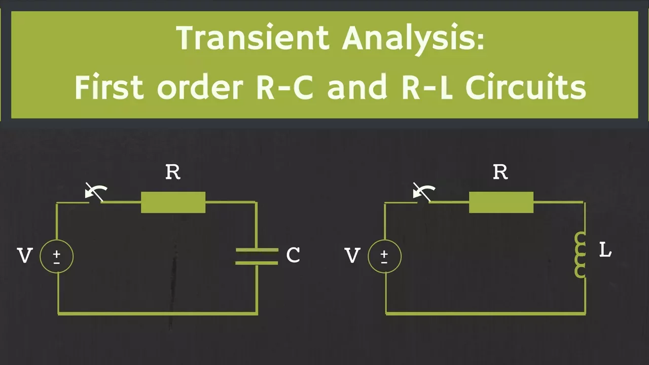
Please watch the following sections:
- Forced Response of an RC Circuit (Charging a capacitor):
11:03to17:23 - Forced Response of an RL Circuit (Energizing an inductor):
17:23to21:45
Let's break down what we saw.
Case 1: The RC Circuit (Forced Response)
When the switch closes, a DC voltage is applied to a series RC circuit with an initially uncharged capacitor.
- Initial State (): The capacitor voltage is 0V. The capacitor initially acts like a short circuit to a changing voltage, so the full current flows.
- Final (Steady) State (): The capacitor becomes fully charged and acts as an open circuit. Current stops flowing, and the capacitor voltage equals the source voltage .
- Transient State: The period during which the capacitor charges. The voltage rises exponentially from 0V to .
The complete response for the capacitor voltage is given by:
Here, we can clearly separate the two components:
- Steady-State Response:
- Transient Response:
Notice the transient part has the term , which decays to zero as time progresses. The rate of this decay is determined by the time constant, . After approximately 5 time constants (), the transient term is negligible (), and we consider the circuit to have reached its steady state.
Case 2: The RL Circuit (Forced Response)
When the switch closes, a DC voltage is applied to a series RL circuit. Assume the inductor has no initial current.
- Initial State (): The inductor resists the change in current, so is 0A. It initially acts like an open circuit.
- Final (Steady) State (): The current becomes stable. The inductor acts as a short circuit, and the final current is limited only by the resistor: .
- Transient State: The period during which the current builds up from 0A to .
The complete response for the inductor current is:
Again, we can separate the components:
- Steady-State Response:
- Transient Response:
In this case, the time constant is .
3. A General Formula for First-Order Circuits
You may have noticed a pattern. The response always involves the initial value, the final value, and an exponential term that bridges them. This can be captured in a single, powerful formula that is extremely useful for quickly analyzing first-order circuits.
Please watch the "shortcut method" explained in the video from 21:59 to 23:59.
The general formula for any variable (like or ) in a first-order circuit is:
Let's dissect this formula:
- is the steady-state response.
- is the transient response.
- is the initial value of the variable just after the change.
- is the total change that needs to occur.
- is the exponential decay function that describes how the transition happens over time.
This single equation elegantly combines the concepts of steady-state and transient response and is a cornerstone of first-order circuit analysis.
Conclusion
In this lesson, we established a clear conceptual framework for understanding how first-order circuits respond to change.
Key Takeaways:
- A circuit's complete response is the sum of its transient and steady-state responses.
- The steady-state response is the final, long-term behavior of the circuit after all transitions have ceased.
- The transient response is the temporary, decaying part of the response that takes the circuit from its initial state to its final steady state.
- The duration of the transient response is determined by the circuit's time constant (), which is for RC circuits and for RL circuits.
Preview of the Next Lesson:
Now that you have a strong intuitive grasp of these concepts, we are ready to tackle the underlying mathematics. In our next lesson, we will formally derive the first-order ordinary differential equation (ODE) for an RC circuit with a step input and solve it from first principles to obtain the complete response we analyzed today.