
Good to see you again. In the previous lesson, you repaired the false-split side of segmentation error: two disconnected fragments that EM evidence showed were really one neurite. You used a merge only after checking the local image stack and the 3D morphology.
This lesson addresses the complementary and often riskier situation: a false merge, where one reconstructed object contains material from two biologically distinct neurites. You will learn to detach the incorrectly attached material with a split, choosing between a simple split and a multi-cut split, and then verify that you removed only the contaminating segment.
A false merge is an attachment error, not an incomplete branch
A false merge occurs when automated segmentation crosses a real biological boundary and groups two distinct processes into one object. The EM data have not changed; the error is in how existing image regions have been grouped into a reconstruction.
Your aim is therefore not to erase pixels or destroy a branch. A split changes the grouping so that the target neuron and the wrongly attached material become separate reconstructed objects. Both remain in the dataset, but the target is no longer contaminated by its neighbor.
Use this distinction before editing:
| Case | What the EM stack indicates | What the segmentation indicates | Appropriate response |
|---|---|---|---|
| False split | One continuous cytoplasm/process | Two disconnected objects | Merge |
| False merge | Two processes separated by a membrane or incompatible continuation | One connected object | Split |
| True branch point | Parent and daughter share continuous cellular interior | One connected object | Leave unchanged |
| Uncertain case | Boundary, alignment, or continuation is unclear | Any state | Document; do not edit |
A reconstructed branch that suddenly forms an implausible cross, sharp turn, or extra arbor is a reason to investigate, not proof that it is wrong. The proof comes from the 2D EM sequence: follow both candidate processes across adjacent sections and locate where the segmentation first treats them as connected despite evidence of a separation.
A useful way to frame the claim is:
“This material is currently part of the target reconstruction, but the EM images show it belongs to a different neurite. A bounded split at this attachment should separate the two without removing legitimate target material.”
For a well-supported case, you should be able to identify all four of these before opening an edit tool:
- A trusted target region that definitely belongs to the neuron you are preserving.
- A trusted contaminant region that definitely belongs to a different neurite.
- The approximate attachment zone where the incorrect grouping occurs.
- The likely shape of the desired result in 3D: one target morphology and one detached neighboring fragment.
The 2024 FlyWire Blog examples below are from the BANC dataset, so treat them as visual error patterns rather than as instructions for the particular dataset you are editing. Their central lesson transfers well: geometry can expose a suspicious merger, but the EM stack still decides the case.
Expert Proofreading Tips for the BANC (Brain and Nerve Cord) Dataset – FlyWire Blog
Read these short FlyWire Blog sections to recognize three merger patterns: perpendicular crossings, parallel contacts, and path swaps. They sharpen visual triage; they do not replace local EM verification.
In “X-Shaped, Perpendicular Mergers,” read from the crossing example. Notice why a crossing branch is suspicious rather than automatically wrong. Then read all of “H-Shaped, Parallel Mergers,” especially the parallel case. Focus on the recommendation to inspect 3D at a local scale rather than trusting a zoomed-out view. Finally, read “Path Swaps.” Start at the path-swap discussion. A path swap is a more complex two-error situation; if you find one, do not treat it as a routine single-cut case.
Choose the smallest tool that fits the topology
FlyWire’s older introductory workflow describes two split methods. The choice is not about speed; it is about the actual structure of the incorrect attachment.
| Tool | Use when | Basic action | Main risk |
|---|---|---|---|
| Simple Split | The contaminant touches the target at one clear, localized connection | Select one side of the attachment, then the other | Mistaking a real continuation for a single contact |
| Multi-Cut Split | The merger has several contacts, runs in parallel, crosses through another branch, or has an irregular attachment region | Mark representative points on each desired output group, preview, then perform the cut | Placing points on ambiguous or incorrectly grouped material |
A simple split is appropriate only if you can honestly describe the bad connection as a single narrow bridge between otherwise separate components. Do not choose it merely because the interface interaction is shorter.
A multi-cut split is the safer default for complicated geometry. Rather than drawing a line through the image, you provide examples of two groups that must become separate. FlyWire uses those marked regions to propose a graph separation. This is why points must be well inside trusted material and distributed through the relevant local extent, not placed on the suspected boundary itself.
Read FlyWire’s original guide to the Simple Split, Multi-Cut Split, and Find Path tools. The interface has evolved since this guide was published, so use its concepts and confirm the current labels, keyboard focus, tooltips, and permissions in your own viewer.
In “Splitting” and “Simple Split (C),” read the explanation beginning with the limitation of simple splits, then continue through the Simple Split instructions. In particular, follow the two-point procedure and note the guide’s refresh advice after an edit. Next, read all of “Multi-Cut Split.” Begin at the subsection heading and follow the instructions from opening the tool through placing and separating point groups. Pay particular attention to the EM-stack check that selected supervoxels do not span the intended separation, the preview control, and the abort control. For an optional investigation aid, read “Find Path,” from its purpose and limitations. It can help localize an unwanted attachment, but its displayed route is approximate evidence, not a verdict.
Prepare the case before you create a split
Treat this like a narrowly scoped production change: define the expected state before changing shared data. Work only on an authorized proofreading assignment or a designated practice environment.
Record a brief pre-edit note:
| Field | Record |
|---|---|
| Location | Dataset coordinates and a share link if available |
| Current object | Current root identifier or visible object reference |
| Target evidence | Where you verified trusted target material |
| Contaminant evidence | Where you verified the wrongly attached material |
| Error type | False merge |
| Proposed action | Simple split or multi-cut split |
| Expected outcome | The contaminant detaches; the target remains anatomically coherent |
Then revisit the attachment in the image stack. Reduce segmentation opacity enough that membranes and internal texture remain visible. Trace a short distance away from the attachment on both processes in both slice directions. A membrane boundary that persists across several sections is strong evidence; a one-slice apparent gap can reflect image artifacts, alignment, or a difficult viewing angle.
If the target reconstruction is large and the attachment point is hard to find, Find Path may be useful. Place one point on trusted target material and another on the suspected contaminant, then inspect the approximate route it reveals. Use it to locate the likely merger zone. Do not infer that every detail of the displayed path is anatomically correct.
Before committing, inspect 3D at two scales:
- Local scale: Can you see the suspicious cross, parallel bridge, or foreign branch clearly enough to predict what should detach?
- Whole-cell scale: Would detaching this region restore a plausible trajectory, rather than amputate an expected dendrite or axon?
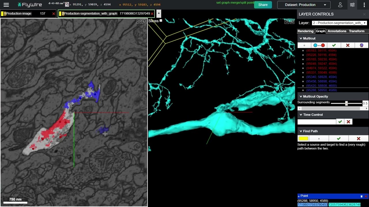
A particularly important stop condition comes from the FlyWire guide: check the EM stack to ensure the selected supervoxels do not span the biological boundary you intend to separate. If the segmentation unit under your proposed point already straddles both sides of that boundary, do not guess with point placement. Record the limitation and seek the appropriate review workflow.
Perform a simple split for a single attachment
Use this method only when the unwanted material touches the target at one unambiguous location.
- Return to the verified attachment zone and ensure that the viewer has keyboard focus.
- Confirm once more which side is the retained target and which is the contaminant.
- Enter Simple Split mode. In the FlyWire 101 guide this is the C key; confirm the active mode in your current interface before clicking.
- Click a point safely inside trusted target material on one side of the attachment.
- Click a point safely inside the trusted contaminant on the other side.
- Wait for the requested edit to process. Do not issue additional clicks while the interface is resolving the operation.
- If the viewer displays the older guide’s dark or black processing region, refresh or reload as directed by the current interface.
- Return to your recorded location and validate the result before doing anything else.
The aim is not simply to make an unwanted protrusion disappear from one viewing angle. Confirm that it now resolves as a separate reconstruction and that the retained target branch still follows the membrane-consistent route you traced before editing.
A simple split is an all-or-nothing claim about that attachment. If there is a second contact nearby, a parallel overlap, or uncertainty about exactly where the two processes are connected, stop and use the multi-cut workflow instead.
Perform a multi-cut split for a complex merger
Multi-cut is suited to the common cases where an incorrect branch is entangled with the target: a cross-shaped merger, an extended side-by-side attachment, or several candidate contacts.
In the FlyWire 101 layout, open the segmentation layer, select the Graph tab, and find the Multi-cut controls. Your current interface may present these controls differently, so rely on its visible labels and hover tooltips rather than memorizing icons.
Mark two clearly different groups
First select the control that places split points. Mark the target group with one color, conventionally red in the older guide:
- Place points in trusted target material, not on a membrane or at the suspected join.
- Use multiple points across adjacent sections when the attachment extends through depth.
- For a small merger, the guide recommends at least three points per side; use more only when the geometry actually requires broader evidence.
- Confirm in 2D that each marked point lies in the intended segmented material.
Then toggle to the other multi-cut group, conventionally blue, and mark the contaminant group with the same discipline. The colors have no biological meaning. They simply state: these marked regions should end up in different reconstructed objects.
For intertwined branches, 2D placement is generally safer because the EM image shows exactly what lies under the point. The guide notes that 3D placement can be appropriate when the branches and their merger are very clearly defined. In a first serious case, prefer 2D unless 3D separation is unmistakable.
Preview before committing
Use Split Preview if the tool offers it. The preview is an opportunity to test the scope of your claim:
- Does the predicted target keep the verified branches it should keep?
- Does the foreign process detach as one coherent component?
- Does the proposed partition cut through a known-good region?
- Are there unexpected extra fragments whose inclusion would change the meaning of the edit?
If the preview is wrong or hard to interpret, use Abort Multi-Cut to clear the points. Re-inspect the EM evidence and revise the case note. Do not turn uncertainty into a sequence of committed experimental cuts.
Once the preview fits the evidence, perform the multi-cut and wait for processing. Reload if needed, then return to the exact saved location rather than judging only from the viewer’s first post-edit camera position.
Validate that the wrong material, and only the wrong material, was removed
A completed split request is not the same as a validated correction. Evaluate the result in this order.
1. Check local 2D evidence
At the original attachment zone, inspect adjacent sections again:
- The target and contaminant should now display as separate reconstructed objects.
- The EM evidence should still support the separation.
- No legitimate target continuation should have been assigned to the detached object.
2. Check 3D morphology
Inspect the reconstructed target locally and as a whole:
- The former contaminant should no longer create an implausible crossing, side bridge, or foreign arbor.
- The retained target should not have a new unnatural stump, large missing subtree, or broken trajectory.
- The detached object should look plausibly independent rather than like a random mixture of target and contaminant branches.
3. Re-identify the edited objects
A split can change current root identifiers. Record the post-edit identity of:
- the target reconstruction you intend to continue proofreading;
- the detached segment or new root, where visible;
- the resulting edit status and time, if your workflow provides it.
Do not assume the pre-edit root ID remains the target’s current identifier. Any later annotation or Python analysis must resolve the current object against the appropriate versioned state.
4. Write the audit note immediately
A concise entry might read:
“False merge split at recorded coordinates. Adjacent EM sections show a membrane-separated perpendicular neurite incorrectly attached to the target. Multi-cut used with target and contaminant points placed in 2D across the local contact. Post-edit review confirms separation in 2D and removes the foreign branch in 3D; target morphology remains continuous. Post-edit roots recorded.”
If the result is ambiguous, record that honestly:
“Split executed, but post-edit membership near the attachment remains unclear because the selected segmentation unit spans the suspected boundary. No additional edit attempted; case flagged for review.”
That is a stronger contribution than a speculative correction.
Cases to leave unchanged
Do not split when any of these apply:
- You can see a possible membrane boundary in one slice but cannot follow it through neighboring sections.
- The putative contaminant might be a genuine branch that leaves the image plane.
- Several nearby processes are plausible contaminants and you cannot identify the specific material under the intended split points.
- A selected supervoxel appears to span the desired biological separation.
- The 3D view suggests a path swap, where the reconstruction follows the wrong continuation while the correct continuation is also missing.
A path swap often requires a coordinated, evidence-backed repair: attaching the correct continuation and separating the incorrect one. Since that is no longer a bounded single-split case, document it and follow the task’s review policy rather than improvising a sequence of edits.
Key takeaways
- A false merge combines biologically distinct material into one reconstruction; a split separates the grouping but does not delete EM data.
- Use a Simple Split only for one clear point of contact. Use Multi-Cut for crossings, parallel attachments, and other complex mergers.
- Mark split points inside trusted target and contaminant material, preferably in 2D, and verify that selected supervoxels do not span the intended boundary.
- Preview a multi-cut when available; abort and reassess rather than committing speculative edits.
- Validate every completed split in adjacent EM sections, local 3D, whole-cell 3D, and current object identity.
- Record both the evidence and the outcome, including unresolved uncertainty.
Next, you will inspect the resulting morphology more systematically to detect unintended consequences of an edit before considering the case complete.
Can't find a good explanation? Sign up and we'll make it for you
Sign up