
Welcome back. In the previous lesson, you used lspci -D -t to reconstruct the logical bridge path from the root complex to a NIC or storage-controller endpoint. That path tells you which links traffic traverses. This lesson gives you a way to quantify each link’s ideal capacity from its negotiated PCIe generation and lane width.
The target is deliberately narrow: per-direction bandwidth after line encoding, before packet and protocol overhead. That makes it a reliable first calculation when a link is unexpectedly narrow or slow. Later, you will account for packet overhead, payload size, read behavior, and other effects that reduce application-observed throughput.
A PCIe link is full duplex, and width is per direction
PCIe is a point-to-point serial interconnect. A device does not share one parallel bus with every other device; it has a link to its immediate neighbor, such as an endpoint to a switch downstream port or a switch upstream port to a root port.
Watch “PCI Express Physical Layer” from Summit Soft Consulting for a compact visual introduction to PCIe’s point-to-point links, generations, and lane terminology.
Watch link scaling to connect generation rate with the use of multiple lanes. Then watch lanes and links, focusing on the distinction between one bidirectional lane and a link made from several lanes.
A lane has independent transmit and receive paths. Consequently, an x4 link has:
- four lanes carrying traffic from device A to device B;
- four separate lanes carrying traffic from device B to device A.
This is why PCIe bandwidth is normally stated per direction. An x4 Gen4 link has approximately available in each direction after line encoding, not split between send and receive.
If both directions carry sustained traffic simultaneously, the ideal aggregate rate is twice the per-direction figure. Keep that as a separate number: most device data sheets and troubleshooting discussions use the per-direction value.
A link’s width is written as x1, x2, x4, x8, or x16. It means “this many active lanes,” not a multiplier applied to one shared channel.
From signaling rate to encoded bandwidth
The generation identifies the signaling rate per lane. For PCIe Gen1 through Gen5, the rates relevant to ordinary bandwidth calculations are:
| Generation | Nominal signaling rate per lane | Line encoding |
|---|---|---|
| Gen1 | 8b/10b | |
| Gen2 | 8b/10b | |
| Gen3 | 128b/130b | |
| Gen4 | 128b/130b | |
| Gen5 | 128b/130b |
GT/s means giga-transfers per second. It is a signaling rate, not a byte rate. For the NRZ signaling used by Gen1 through Gen5, it is numerically usable as gigabits per second per lane before line encoding.
Line encoding adds bits that help the receiver recover clock timing and maintain a usable electrical signal. Those bits consume part of the serial link capacity.
For Gen1 and Gen2, 8 useful bits require 10 transmitted bits:
So Gen1’s becomes:
For Gen3 through Gen5, 128 useful bits require 130 transmitted bits:
The encoding cost is only about , far lower than the cost of 8b/10b. This encoding change is one reason Gen3 gained substantially more useful bandwidth than a simple comparison of raw signaling rates might suggest.
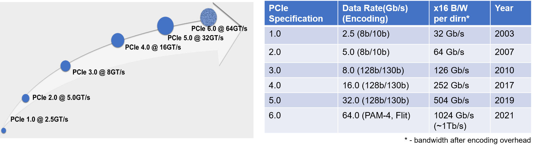
The chart gives a useful sanity check. For example:
- Gen3 x16 is about , or about , per direction.
- Gen4 x16 is about , or about , per direction.
- Gen5 x16 is about , or about , per direction.
Notice that Gen3 x16 does not equal after encoding. The small difference is the 128b/130b overhead.
The calculation to use
For Gen1 through Gen5, calculate ideal per-direction encoded bandwidth as:
where:
- is per-direction bandwidth in ;
- is the generation’s transfer rate in ;
- is the encoding efficiency;
- is the negotiated lane width;
- division by 8 converts gigabits per second to gigabytes per second.
PCIe performance figures conventionally use decimal units here:
Do not introduce a factor of two into this formula. The formula already gives the capacity of one direction. Double it only when you explicitly want ideal simultaneous bidirectional aggregate bandwidth.
Worked example: Gen4 x4
Suppose an endpoint is connected to a switch downstream port at Gen4 x4.
First calculate the encoded bit rate:
Then convert to bytes:
Rounded suitably:
The ideal simultaneous aggregate in both directions would be about , but retain as the normal per-direction link figure.
Worked example: Gen2 x8
Gen2 uses 8b/10b:
The division by 8 for byte conversion happens to cancel the x8 lane multiplier in this particular example. That is arithmetic coincidence, not a general shortcut.
Worked example: Gen5 x16
This agrees with the PCI-SIG chart’s rounded x16 result of , or approximately , per direction.
A practical reference table
The following values are per lane, per direction, after line encoding and before packet overhead.
| Generation | Encoded rate per lane | Bandwidth per lane |
|---|---|---|
| Gen1 | ||
| Gen2 | ||
| Gen3 | ||
| Gen4 | ||
| Gen5 |
For a particular link, multiply the last column by its width:
| Link | Calculation | Ideal encoded bandwidth per direction |
|---|---|---|
| Gen3 x4 | ||
| Gen3 x8 | ||
| Gen4 x4 | ||
| Gen4 x8 | ||
| Gen4 x16 | ||
| Gen5 x4 | ||
| Gen5 x8 | ||
| Gen5 x16 |
These equivalences are useful operational shortcuts:
- Gen4 x4 and Gen3 x8 both provide about per direction.
- Gen5 x4 and Gen4 x8 both provide about per direction.
- Halving width halves the ideal bandwidth; dropping one generation approximately halves it as well.
Gen6: use the published rate carefully
PCIe 6.0 uses PAM4 signaling and FLIT-based operation rather than the Gen3–Gen5 128b/130b model. Therefore, do not mechanically apply the Gen1–Gen5 encoding-efficiency formula to a Gen6 rate.
For topology planning, the PCI-SIG chart reports approximately:
for a Gen6 x16 link in one direction, which is approximately:
That corresponds to approximately per lane in the chart’s rounded convention.
For an operational throughput estimate on an actual Gen6 platform, distinguish carefully among the advertised link rate, FLIT/FEC effects, and transaction payload efficiency. The simple Gen1–Gen5 calculation remains the standard quick method for most currently deployed switch, NIC, and storage-controller links.
Use negotiated link status, not slot labels or maximum capability
A physical x16 connector does not guarantee a Gen5 x16 operating link. The actual link can train at fewer lanes or a lower generation because of platform wiring, device capability, bifurcation, signal integrity, adapter design, or a fault.
For the link adjacent to an endpoint or switch port, inspect detailed PCI output:
lspci -D -s 0000:03:00.0 -vv
Replace the example BDF with a real function from your system. Look for lines similar to:
LnkCap: Speed 16GT/s, Width x8
LnkSta: Speed 8GT/s, Width x4
These fields answer different questions:
| Field | Meaning | Use in a capacity calculation |
|---|---|---|
LnkCap | Maximum speed and width the port advertises | Potential capability only |
LnkSta | Currently negotiated speed and width | Use these values for the live link |
In the example, the port is capable of Gen4 x8 but is currently running at Gen3 x4. The correct live calculation is:
It would be incorrect to report the Gen4 x8 capability of about as current capacity.
On a switched system, the endpoint and its immediate upstream switch port describe the same physical link and should normally report compatible status. The endpoint’s LnkSta does not describe every link from the endpoint back to the host. Use the topology path you derived previously and inspect each bridge-to-device link separately.
A path’s end-to-end throughput is limited by its narrowest relevant link. A fast Gen5 x16 host-facing switch link does not make a Gen4 x4 downstream NIC link faster.
Encoded bandwidth is not application throughput
This lesson’s result is a useful ceiling, but it is not the payload throughput that an application will necessarily observe.
The calculation excludes overhead from:
- TLP headers and any optional ECRC;
- Data Link Layer sequence fields and LCRC;
- PHY framing and control traffic;
- flow control, acknowledgements, replay after errors, and idle periods;
- request/completion behavior, especially for reads;
- software, DMA-engine, memory, and device limitations.
For example, a Gen4 x4 NVMe controller has an encoded link ceiling of about per direction. A benchmark below that value is not automatically evidence of a PCIe fault. It may instead reflect storage media, controller firmware, queue depth, transfer size, read-completion behavior, or ordinary protocol overhead.
Conversely, if a system designed for Gen4 x4 reports LnkSta: Speed 8GT/s, Width x1, its encoded ceiling is only:
That observation is immediately significant before any workload benchmark is run.
A short lab workflow
Use the topology record from the previous lesson and select one endpoint plus its immediate upstream bridge or switch port.
-
Inspect detailed output for both functions:
lspci -D -s <endpoint BDF> -vv lspci -D -s <upstream bridge BDF> -vv -
Record
LnkCapandLnkStaspeed and width for the shared physical link. -
Calculate the live encoded per-direction bandwidth using
LnkSta. -
Record the result alongside the endpoint path. A practical inventory entry might include:
endpoint:          0000:03:00.0
immediate port:    0000:02:00.0
negotiated link:   Gen4 x4
encoded capacity:  7.88 GB/s per direction
This is read-only collection. It creates a baseline that will later help distinguish an expected x4 storage-controller link from an accidental downtrain to x1, or a Gen4-capable NIC operating at Gen3.
Key takeaways
- PCIe bandwidth is normally stated per direction because every lane has independent transmit and receive paths.
- For Gen1 through Gen5:
- Use efficiency for Gen1 and Gen2, and for Gen3 through Gen5.
- A Gen4 x4 link provides approximately per direction after encoding; Gen5 x16 provides approximately .
- Use
LnkSta, notLnkCapor the physical connector label, to calculate the capacity of a live link. - Encoded bandwidth is an ideal ceiling before packet, protocol, device, and software overheads.
Next, the course moves into enumeration and configuration space: how Linux discovers PCIe functions, assigns bus numbers, and makes the switched hierarchy usable.
Can't find a good explanation? Sign up and we'll make it for you
Sign up