
Good to see you again. Previously, you learned to decode a Linux PCI function address such as 0000:03:01.0: domain, bus, device, and function. A BDF tells you the current logical location of one function, but not how that function is connected back to the host.
This lesson turns that location into a route. You will use Linux’s PCI tree output to identify the chain of root port and bridge functions between the host and a NIC or storage controller. This is a read-only workflow you can apply directly to switched systems, including systems built around Broadcom/PLX devices. Plan for roughly 40 minutes.
What a Linux PCI tree represents
Run:
lspci -D -t
The -t option asks lspci to print a tree containing buses, bridges, devices, and their connections. The -D option keeps the PCI domain visible, which is useful in logs, scripts, and systems with multiple PCI segments.
Read the relevant lspci options in the official Linux manual page. The tree view is the central tool for this lesson; the path-display options are useful corroboration when a hierarchy is deep.
In the DESCRIPTION section under “Basic display modes,” read the tree option. Focus on what -t includes: buses, bridges, devices, and connections. Later in the option list, in the display-options material, read the domain and path options. Note the distinct purposes of -D, -P, and -PP; for now, use -D -t as the primary topology view.
A simplified tree might look like this:
-[0000:00]-+-00.0
           +-01.0-[01-03]----00.0-[02-03]----00.0-[03]----00.0
           \-14.0
The punctuation is a compact drawing convention. Its essential meaning is hierarchical:
[0000:00]is the root bus for PCI domain0000. It is not a function BDF because it has no device/function portion.00.0,01.0, and14.0are functions on the bus currently being shown.- A function followed by a bracketed bus range, such as
01.0-[01-03], is a bridge function leading to a downstream hierarchy. - The final
00.0in the long branch has no bracketed bus range, so it is a leaf in this particular path. It may be an endpoint, subject to verification with normallspcioutput.
The PCI tree is a logical routing hierarchy. It is not a diagram of motherboard traces, switch packages, or chassis slots. But it is exactly the hierarchy Linux uses to locate a device and to determine the bridges through which requests must travel.
Read the tree relative to its current bus
The main challenge is that lspci -t does not repeat the full BDF for every node. Instead, each DD.F label inherits the bus number from its position in the tree.
Use this rule:
To reconstruct a node’s full BDF, combine the domain and the current bus context with the
device.functionprinted at that node.
In the example above, trace the long branch one level at a time.
| Tree fragment | Current bus context | Full BDF reconstructed | Interpretation |
|---|---|---|---|
[0000:00] | 00 | Root bus, not a function | Start of this PCI domain’s hierarchy |
01.0-[01-03] | 00 | 0000:00:01.0 | A bridge function on bus 00 |
00.0-[02-03] | 01 | 0000:01:00.0 | A bridge function on bus 01 |
00.0-[03] | 02 | 0000:02:00.0 | A bridge function on bus 02 |
00.0 | 03 | 0000:03:00.0 | A leaf function on bus 03 |
So the host-to-endpoint path is:
- The host/root-complex side owns root bus
0000:00. - The hierarchy passes through bridge function
0000:00:01.0. - It then passes through bridge function
0000:01:00.0. - It then passes through bridge function
0000:02:00.0. - The destination function is
0000:03:00.0.
In a production system, the first bridge may be a root port, while the later bridge functions may be ports belonging to one or more PCIe switches. The tree alone tells you there are bridges; detailed information is needed to establish whether a particular bridge is a root port, a Broadcom/PLX switch port, or another kind of bridge.
Bracketed bus ranges: useful context, not extra devices
Consider this fragment:
01.0-[01-03]
It means that the function 01.0 on the current bus is a bridge whose downstream hierarchy covers buses 01 through 03.
Do not read [01-03] as three devices or three individual links. It is a bus-number range allocated to the hierarchy below that bridge. The next function immediately following the bracket is found on the bridge’s direct downstream bus, here bus 01.
In the example:
0000:00:01.0  covers buses 01 through 03
0000:01:00.0  covers buses 02 through 03
0000:02:00.0  covers bus 03
0000:03:00.0  is the final function
The range narrows as the path descends because each bridge owns a portion of the overall hierarchy. In the next module, you will inspect the actual Primary, Secondary, and Subordinate Bus Number fields in bridge configuration space. For this lesson, treat the bracketed range as a navigation aid in the tree.
A switched NIC or storage-controller path
A PCIe switch creates a hierarchy that Linux represents with multiple PCI bridge functions. This is why a switch is often visible as several BDFs rather than one single “switch BDF.”
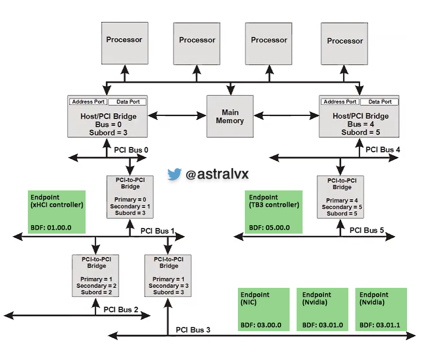
In the diagram’s left hierarchy, the NIC endpoint is labeled 03.00.0. With Linux’s domain included, its BDF is:
0000:03:00.0
The logical route is:
| Order | Function or bus | Role in the route |
|---|---|---|
| 1 | Root bus 0000:00 | Root-complex-side bus |
| 2 | Bridge on bus 00 | Introduces bus 01 |
| 3 | Bridge on bus 01 | Introduces bus 03 through its downstream hierarchy |
| 4 | 0000:03:00.0 | NIC endpoint |
The diagram also shows two NVIDIA functions:
0000:03:01.0
0000:03:01.1
These share the same upstream path through the hierarchy because they are on the same bus and device, but they are still distinct functions. Your management software must inventory, monitor, and potentially bind drivers for each function independently.
A storage controller behaves the same way from the tree’s perspective: identify its BDF, find its leaf position, then walk upward through each enclosing bridge branch until reaching the domain’s root bus.
A repeatable Linux workflow
Use this workflow on lab hardware. It makes no configuration changes.
1. Capture the topology tree
lspci -D -t | tee pcie-tree.txt
Saving the output is useful when troubleshooting: it gives you a topology snapshot that can be compared with a later system state.
2. Find the endpoint’s full BDF
Use a normal listing because the tree view intentionally compresses BDFs:
lspci -D -nn
For an endpoint of interest, record the full BDF. For example:
EP=0000:03:00.0
Do not use this example value unless it exists on your host.
Then verify the function’s identity:
lspci -D -s "$EP" -nn -vv
For a NIC, expect a class such as Ethernet controller. For storage hardware, the class may identify an NVMe controller, RAID bus controller, SAS controller, or another storage-related device. The detailed output also helps distinguish a true endpoint from a bridge function.
3. Locate the endpoint branch in the tree
Open pcie-tree.txt and find the branch whose final bus matches the endpoint bus in $EP.
For an endpoint at 0000:03:00.0, start from root bus [0000:00] and follow the indented branch until you reach bus 03 and its 00.0 function. Record every preceding function with a bracketed downstream bus range. Those are the bridge functions on the path.
A useful record has this form:
| Sequence | Full BDF | Provisional topology role | Evidence |
|---|---|---|---|
| 1 | 0000:00:01.0 | Root-port or bridge candidate | Bridge node in tree; verify with detailed lspci |
| 2 | 0000:01:00.0 | Bridge or switch-port candidate | Encloses the endpoint’s subtree |
| 3 | 0000:02:00.0 | Bridge or switch-port candidate | Encloses the endpoint’s subtree |
| 4 | 0000:03:00.0 | Target endpoint | Endpoint class from detailed lspci |
“Candidate” is deliberate. Do not call a bridge a PLX port simply because it lies between the host and a NIC. Verify its vendor/device IDs and detailed capabilities:
lspci -D -s 0000:01:00.0 -nn -vv
A Broadcom/PLX switch port often appears as a PCI bridge whose vendor ID is associated with Broadcom or legacy PLX Technology identifiers. Exact names depend on the switch family and the local PCI ID database.
4. Cross-check with bridge-path output
The lspci manual also documents -P and -PP, which identify devices by their path through bridges. Use them as a second view when the regular tree is dense:
lspci -D -PP -s "$EP" -nn
This does not replace understanding the tree. It is a diagnostic cross-check that makes the bridge path more explicit for a selected endpoint.
Avoid four common interpretation errors
1. Treating the root bus as a root-port BDF
[0000:00] is a domain and bus context, not a PCI function. A root port, if present in the path, is a child bridge function such as 0000:00:01.0.
2. Forgetting the inherited bus number
A leaf shown as 00.0 is not automatically 0000:00:00.0. Its bus is determined by the level at which it appears. In the worked example, the final 00.0 is 0000:03:00.0.
3. Confusing a bus range with a sequence of bridge functions
[01-03] says the bridge’s subtree uses bus numbers 01 through 03. It does not mean that buses 01, 02, and 03 all contain one bridge on the chosen path. Follow indentation and branch structure to determine the actual route.
4. Assuming the tree proves physical wiring or switch-port numbering
The PCI hierarchy proves Linux’s enumerated logical route. It does not, by itself, tell you which physical connector, cable, or PLX port number is involved. Mapping logical bridge BDFs to vendor-specific port numbers requires switch documentation and vendor management registers, which you will address later in the course.
Build a topology record suitable for software
For a management application, retain the path as ordered structured data rather than a formatted string. A compact conceptual representation is:
struct PciAddress {
    uint16_t domain;
    uint8_t  bus;
    uint8_t  device;
    uint8_t  function;
};

struct EndpointPath {
    PciAddress endpoint;
    std::vector<PciAddress> upstream_bridges;
};
For endpoint 0000:03:00.0, the upstream_bridges list should be ordered from host-facing to endpoint-facing:
0000:00:01.0
0000:01:00.0
0000:02:00.0
This ordering becomes operationally valuable later:
- A link issue reported by a bridge can be associated with all endpoints below that bridge.
- An endpoint removal can be correlated with its immediate upstream port.
- Inventory can distinguish two identical NICs based on their live topology paths.
- A switch-health snapshot can attach per-port status to the endpoints affected by that port.
For now, keep the data read-only and observational. Enumeration, resource windows, link status, resets, and vendor-specific switch management each build on this path model later.
Key takeaways
lspci -D -tshows the Linux PCI hierarchy as buses, bridge functions, and endpoint functions.- The root tree label, such as
[0000:00], is a domain-plus-bus context, not a complete BDF. - A
DD.Fnode inherits its bus number from its position in the tree; combine that bus with the domain to reconstruct its full BDF. - A function followed by a bracketed bus range is a bridge leading to a downstream hierarchy.
- To derive a host-to-endpoint path, start at the endpoint leaf and identify each enclosing bridge branch back to the root bus.
- Confirm tree-derived roles with
lspci -D -s <BDF> -nn -vv; the tree establishes the route, while detailed output establishes device identity.
Next, you will quantify the capacity of the links in that path by calculating per-direction PCIe bandwidth from generation and lane width.
Can't find a good explanation? Sign up and we'll make it for you
Sign up