
Welcome. This course builds the PCIe mental model needed to manage switched NIC and storage-controller systems from Linux: first recognizing the hardware hierarchy, then learning enumeration, configuration space, switch routing, link health, and Broadcom/PLX management.
This first lesson establishes the vocabulary you will use in every topology diagram, lspci tree, register manual, and troubleshooting log: root complex, root port, PCIe switch, upstream port, downstream port, and endpoint. By the end, you should be able to label a direct-attached device and a switch-based fan-out topology without treating “upstream” and “downstream” as traffic directions.
Plan for roughly 35–40 minutes.
PCIe is a hierarchy of dedicated links
PCIe is not a single shared bus like conventional PCI. It is a hierarchy of point-to-point, full-duplex links. Each link joins exactly two PCIe interfaces, and a platform grows by adding branches to that hierarchy.
For the systems relevant to NIC and storage management, the basic shape is:
- The host platform exposes PCIe connectivity through a Root Complex.
- A Root Complex port may connect directly to a device, such as an NVMe controller or NIC.
- Alternatively, that port may connect to a PCIe switch.
- The switch fans the connection out to several downstream devices.
The hierarchy supplies a stable point of reference:
- Upstream means toward the Root Complex.
- Downstream means away from the Root Complex, toward leaf devices.
Those labels describe a component’s position in the topology, not the direction of the bits at a given moment. A NIC performing DMA writes to host memory sends traffic toward the Root Complex, yet it remains a downstream endpoint in the hierarchy.
PCIe Protocol – PCI Express Explained
Read the “PCIe Topology” section from Ecrionix as a concise first account of PCIe’s tree structure and the roles of Root Complexes, switches, and endpoints.
In Section 2, “PCIe Topology,” read from the topology introduction through the topology rules. Focus on the distinction between a Root Complex at the top, an optional switch that creates branches, and endpoint devices at the leaves. Leave the later material on lanes for a future lesson.
The components to label
Root Complex: the host-side origin of a PCIe hierarchy
The Root Complex (RC) is the host-side PCIe controller that connects the CPU and system memory to the PCIe fabric. On a current server, it is commonly integrated into the CPU or SoC; on other platforms, some PCIe connectivity may be provided through a chipset.
The important practical point is not the exact silicon packaging. When looking at a topology, the Root Complex is the top-most host-side component from which that PCIe branch begins.
A single platform can contain multiple Root Complex ports. For example, one root port can connect directly to a boot NVMe drive while another connects to a PLX switch that serves several NICs. Each root port begins a distinct branch of the host’s PCIe hierarchy.
Root Port: the Root Complex’s PCIe-facing port
A Root Port is a PCIe port belonging to the Root Complex. It is the physical/logical interface through which the Root Complex connects to a downstream PCIe link.
From the hierarchy’s perspective, a Root Port is a Downstream Port: it faces away from the Root Complex and toward devices.
This distinction matters in Linux and in documentation:
- Root Complex names the host-side PCIe subsystem.
- Root Port names one particular PCIe port within that subsystem.
- A platform may have many Root Ports but only one host-side Root Complex implementation for a given hierarchy.
Endpoint: a leaf PCIe device
An Endpoint is a terminal device on a PCIe branch. Familiar examples include:
- Ethernet NICs
- NVMe SSD controllers
- RAID or storage controllers
- GPUs
- FPGA accelerator cards
An endpoint normally has no PCIe path to further downstream PCIe devices. It is therefore a leaf in the tree.
“Endpoint” does not mean “only receives data.” A NIC, storage controller, or accelerator can initiate memory accesses, including DMA to host memory. The term describes its topological role, not whether it can request or transmit traffic.
A device can also expose more than one PCIe function. Later, Linux will identify such functions using Bus:Device.Function addresses. For now, treat a multi-function NIC as one physical endpoint device that may expose several software-visible functions.
PCIe switch: a fan-out point
A PCIe switch takes one host-facing PCIe connection and provides several device-facing PCIe connections. It makes it possible to attach more endpoints than the Root Complex’s directly available ports would otherwise allow.
A switch is neither the Root Complex nor a leaf endpoint. It is an internal branching component in the PCIe hierarchy.
For a typical single-host switch topology:
- The switch has one Upstream Port facing the Root Complex.
- The switch has one or more Downstream Ports facing endpoints or further switches.
Each switch port participates in its own point-to-point link. A switch is not a passive splitter: it contains logic that forwards traffic between the appropriate ports.
Labeling ports without ambiguity
The following table is a reliable reference when inspecting a diagram or a board design.
| Link connection | Port at the host-facing side | Port at the device-facing side |
|---|---|---|
| Root Complex connected directly to a NIC or SSD | Root Port, which is a Downstream Port | Endpoint’s upstream-facing PCIe interface |
| Root Complex connected to a PCIe switch | Root Port, which is a Downstream Port | Switch Upstream Port |
| PCIe switch connected to a NIC or SSD | Switch Downstream Port | Endpoint’s upstream-facing PCIe interface |
| One PCIe switch connected below another switch | Upstream switch Downstream Port | Downstream switch Upstream Port |
One terminology nuance will prevent confusion in vendor manuals:
Upstream Port is a formal PCIe switch-port type. An endpoint’s only PCIe interface also faces upstream toward the host, and diagrams often label it “upstream port,” but the endpoint remains an Endpoint, not a Switch Upstream Port.
The diagram below shows both the simplest direct-attached case and a switched case.
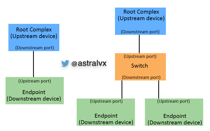
Read the diagram vertically:
- Left side: the Root Complex is at the top; its Root Port is downstream-facing. The green device is the endpoint at the bottom.
- Right side: the Root Complex is again at the top. The orange switch sits in the middle, with its one Upstream Port at the top and its Downstream Ports below. The two green devices are endpoints.
The diagram’s use of “upstream device” for the Root Complex and “downstream device” for endpoints is useful shorthand for placement. In day-to-day engineering work, prefer the more precise component names: Root Complex/Root Port, Switch Upstream Port, Switch Downstream Port, and Endpoint.
Overview of PCI(e) Subsystem - Kishon Vijay Abraham, Texas Instruments
Watch “Overview of PCI(e) Subsystem” by Kishon Vijay Abraham on The Linux Foundation channel for a visual walkthrough of the Root Complex, endpoints, root ports, and a switch-connected branch.
Watch the terminology for concise definitions of the Root Complex, endpoint, bridge, and switch. Then watch the topology diagram. Focus on how one Root Complex can have multiple Root Ports: one may attach directly to an endpoint while another attaches to a switch that serves several endpoints.
A concrete Broadcom/PLX-style example
Consider a server CPU with an PCIe Root Port connected to a Broadcom/PLX PEX 8525 switch. The switch uses that host-facing connection as its Upstream Port and can fan it out into several narrower Downstream Ports, for example four links. Each link could lead to a separate NIC, NVMe controller, FPGA, or an embedded module.
In that topology, label the components as follows:
| Item | Correct label | Why |
|---|---|---|
| CPU-integrated PCIe host controller | Root Complex | It originates the PCIe hierarchy from the host side. |
| connection leaving the host toward the switch | Root Port / Downstream Port | It belongs to the Root Complex and faces into the PCIe hierarchy. |
| Host-facing interface on the PEX 8525 | Switch Upstream Port | It is the switch port nearest the Root Complex. |
| Each PEX 8525 interface leading to a NIC or storage controller | Switch Downstream Port | It leads away from the Root Complex toward a leaf device. |
| NIC or storage controller | Endpoint | It terminates that branch of the PCIe hierarchy. |
The switch can be physically a single chip, but software and PCIe documentation often discuss its ports individually. This is why switch register manuals frequently organize information by port number: link state, error counters, reset controls, and lane configuration may differ for each logical port.
[PDF] PEX 8525 - Support Documents and Downloads
Read the PEX 8525 “Host Centric Fan-out” example to connect the generic topology vocabulary to a Broadcom/PLX switch configuration.
In the “Host Centric Fan-out” discussion, locate the paragraph beginning “Figure 2 shows a typical server-based design.” Read the PEX 8525 fan-out example. Ignore the dense figure details for now. Identify the single host-facing x8 link as the switch’s upstream connection and the four x4 device-facing links as downstream connections.
A repeatable topology-labeling method
When you encounter a board block diagram, a PLX design guide, or eventually Linux topology output, use this method.
-
Find the host-side origin. Look for the CPU, SoC, chipset PCIe controller, or an explicit Root Complex label. That is the top of the branch.
-
Find direct neighbors of the Root Complex. Each host PCIe connection leaves via a Root Port. A direct neighbor is either an endpoint or a switch.
-
Identify fan-out devices. A component with one host-facing PCIe connection and several device-facing PCIe connections is a switch. Its host-facing port is its Upstream Port.
-
Label every switch-to-device connection. The switch side is a Downstream Port. The device at the far end is an Endpoint.
-
Stop at leaves. A NIC, NVMe controller, GPU, or similar terminal device is an endpoint. It may have multiple functions and may initiate DMA, but it has no PCIe descendants in this topology.
-
Verify the link pairing. A valid pair should make sense on both ends: Root Port with Endpoint, Root Port with Switch Upstream Port, or Switch Downstream Port with Endpoint.
This method avoids a common mistake: calling a PCIe slot, cable, or lane group “the switch port” without saying which side of the link is being discussed. A link has two ends, and the roles at those ends are different.
What this means for management and troubleshooting
Your future management application will not merely inventory “a PLX switch.” It will need to associate each port with its place in the hierarchy:
- Which Root Port leads to this switch?
- Which switch Downstream Port leads to a particular NIC or storage controller?
- Is a missing endpoint absent because its switch port has no active link, or because the host cannot enumerate a device beyond an otherwise active port?
- Is a port-level error reported at the host-facing switch port or at the downstream port attached to the affected controller?
Before collecting registers or issuing a management operation, make a simple topology sketch with the Root Complex at the top, the switch in the middle if present, and endpoints at the leaves. Add known port numbers only when the board documentation gives a trustworthy mapping. This separates the logical PCIe hierarchy from physical slot names and PCB connector labels, which are not always the same thing.
You now have the essential topology vocabulary:
- The Root Complex connects host CPU/memory resources to PCIe.
- A Root Port is a Root Complex port and is downstream-facing.
- A PCIe switch creates branches, with one host-facing Upstream Port and multiple device-facing Downstream Ports.
- A PCIe endpoint is a leaf device such as a NIC or storage controller.
- “Upstream” and “downstream” describe position relative to the Root Complex, not instantaneous traffic direction.
Next, we will look inside each PCIe connection by separating the transaction, data-link, and physical layers. That model will make later discussions of configuration reads, link status, acknowledgements, and errors much easier to place.
Can't find a good explanation? Sign up and we'll make it for you
Sign up