
Hello. In the previous lesson, you established the shape of a PCIe system: the Root Complex sits at the host side, switches create branches, and NICs or storage controllers are endpoints. We now look inside every one of those point-to-point links.
This lesson explains why PCIe divides its protocol into the Transaction, Data Link, and Physical layers. The distinction is practical: transaction-layer concepts will appear in configuration and MMIO accesses; data-link behavior explains retries and link-local integrity; physical-layer behavior explains training, lane width, speed, and signal-related failures. Plan for about 35–40 minutes.
One PCIe request, three different jobs
A Linux driver may read a device register, configure a switch port, or let a NIC DMA data to system memory. At the software level, that appears to be one operation. PCIe makes it work by dividing responsibility into layers.
The three layers answer different questions:
| Layer | Core question | Main responsibility |
|---|---|---|
| Transaction | What operation is being requested, and where should it go? | Forms requests and responses as Transaction Layer Packets (TLPs). |
| Data Link | Did this neighboring port receive the packet correctly, without overflowing? | Link-local integrity, acknowledgement, retry, and credit updates. |
| Physical | How are bits actually conveyed across this electrical link? | Link training, encoding, serialization, and differential electrical signaling. |
The key distinction is scope:
- The Transaction Layer provides the meaningful PCIe operation that can travel across a hierarchy, such as a host-to-endpoint memory access through a switch.
- The Data Link Layer operates separately on each individual link. A host Root Port to switch link and a switch to NIC link each have their own Data Link Layer state.
- The Physical Layer operates at the actual electrical connection between the two ports of one link.
This is comparable to working with a managed network switch, with an important caveat: PCIe is a tightly specified hardware interconnect rather than Ethernet. The transaction layer carries the operation’s meaning, each hop protects local delivery, and the physical layer turns data into signals on a particular connection.
PCI Express Gen 1 to Gen 3 Architecture | Layered Protocols Stacks PCIe
Watch “PCI Express Gen 1 to Gen 3 Architecture | Layered Protocols Stacks PCIe” from GogoTraining - PeopleCert Accredited (ATO). It provides a compact visual orientation to the three layers, especially the difference between end-to-end transactions and link-local reliability.
Start with the overview for the role of each layer. Then watch layer scope, which contrasts transaction-layer service with the per-link Data Link Layer. Watch physical transmission for the conversion to signals, and finish with port stacks to see why every Root Port and switch port needs the layered stack.
Encapsulation: the packet changes as it descends the stack
At transmission, information moves downward from Transaction to Data Link to Physical. At reception, the reverse happens: the receiving Physical Layer recovers data from the link, the Data Link Layer validates it, and the Transaction Layer interprets the PCIe request or response.

The diagram is useful, but read it with one rule in mind: the TLP is the transaction-layer object; sequence numbers, link CRCs, acknowledgements, and physical signaling belong to lower layers.
A simplified transmission view is:
- The Transaction Layer creates the TLP containing the requested operation.
- The Data Link Layer protects that TLP for one link.
- The Physical Layer places the protected stream onto the lanes.
At the far end of the link, these lower-layer additions are consumed. If the next component is a switch, the switch routes the received TLP and sends it onward across another PCIe link, where new link-local protection is applied.
PCIe Protocol – PCI Express Explained
Read the “PCIe Protocol – PCI Express Explained” overview from Ecrionix to consolidate the responsibility of each layer before examining their behavior in a switched hierarchy.
In the section beginning just below “Fig 2 — PCIe 3-layer architecture,” read the three layer descriptions. Focus on the different packet types: TLPs express useful requests and responses, whereas DLLPs carry link-management information such as acknowledgements and flow-control updates.
The Transaction Layer: expressing PCIe operations
The Transaction Layer is closest to the behavior that software intends. It turns an operation into a Transaction Layer Packet, or TLP.
A TLP contains the information needed for PCIe components to understand the operation. Its header identifies such things as the request type, addressing or destination information, attributes, and length. Some TLPs also carry a data payload.
For the systems you will manage, common transaction-layer activities include:
- A host reading or writing a switch or endpoint register through a BAR-mapped MMIO region.
- Firmware or Linux enumerating functions through configuration transactions.
- A NIC writing received network data into host memory with DMA.
- An NVMe controller reading command data from host memory or writing completion data back.
- A PCIe component reporting an event through a message transaction.
The Transaction Layer does not decide the voltage swing on a lane or directly wait for an electrical acknowledgement. Its responsibility is to represent the intended operation in a packet form that can be routed through the PCIe hierarchy and interpreted by the final receiver.
TLPs carry meaning; lower-layer packets do not
It is useful to distinguish TLPs from DLLPs now:
- A TLP carries a PCIe request, response, configuration access, memory operation, or message. Transaction Layers create and consume TLPs.
- A DLLP, or Data Link Layer Packet, carries link-management information, including acknowledgements, negative acknowledgements, and flow-control updates. Transaction Layers normally never see DLLPs.
The core of a TLP is created at the Transaction Layer.
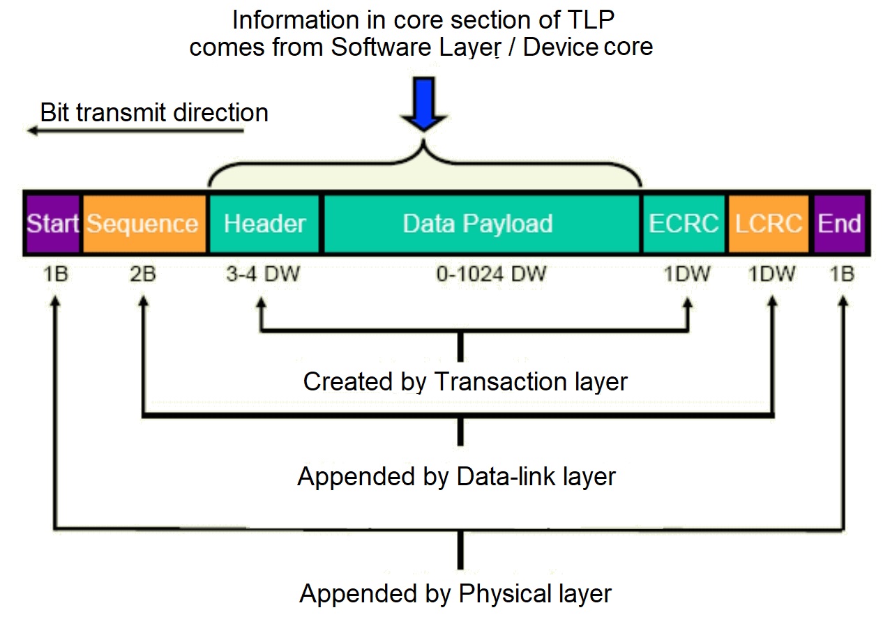
The figure’s division of responsibility is more important than memorizing field sizes. For example, a driver issuing an MMIO write determines neither the Sequence field nor the LCRC. The PCIe hardware associated with the sending port handles those automatically.
Flow control protects receiver capacity
The Transaction Layer must also respect the capacity of the receiver. PCIe uses credit-based flow control: a receiver advertises how much buffering it has available, and a sender transmits a TLP only when it holds the required credit.
This prevents a fast sender from overflowing a receiver’s buffers. The actual updates travel in Data Link Layer Packets, but their effect is to control when the Transaction Layer is permitted to send a packet.
For switch management, this distinction matters because a lack of throughput is not automatically a link-speed issue. A link can be electrically healthy while traffic is constrained by available credits, packet sizing, routing, or congestion elsewhere in the switch. Performance analysis later in the course will build on this separation.
The Data Link Layer: reliable delivery over one link
The Data Link Layer takes a TLP and ensures its reliable delivery to the immediately adjacent port. Its scope is deliberately local.
For each outbound TLP, the Data Link Layer typically:
- Adds a sequence number, allowing the receiver to identify packet order and detect a missing or duplicate transmission.
- Adds an LCRC (Link Cyclic Redundancy Check), which allows the receiver to detect corruption on that specific PCIe link.
- Retains the transmitted TLP in a replay buffer until the neighboring receiver acknowledges it.
- Receives or sends DLLPs that convey ACK, NAK, and flow-control information.
When the receiver validates a TLP, it sends an ACK DLLP. If the receiver detects an error, it can send a NAK DLLP. If an ACK does not arrive before a timer expires, the sender can retransmit the stored TLP from its replay buffer.
Two practical cautions follow.
An ACK is not a device-operation completion
Suppose software writes a control register in a storage controller. An ACK from the Data Link Layer means the neighboring PCIe port received that packet correctly on that link. It does not mean that the storage-controller firmware has completed the operation requested by that write.
Link reliability and device-level completion are separate concepts. This prevents a common troubleshooting error: treating a healthy stream of link acknowledgements as proof that the endpoint’s driver or firmware has successfully acted on a command.
Data Link reliability restarts at every switch port
Consider a host connected through a PLX switch to an endpoint:
Root Port — Switch Upstream Port | Switch Downstream Port — Endpoint
There are two independent PCIe links here. The switch validates traffic arriving at its Upstream Port using the Data Link Layer for the host-facing link. Once the Transaction Layer in the switch has accepted and routed the TLP, the switch’s Downstream Port transmits it over its own link using a new sequence number and LCRC.
Therefore:
- A bad cable, connector, lane, or receiver on one downstream link causes replay activity on that link.
- It does not cause the Root Port to replay traffic across the host-facing link.
- Error reporting and counters must be associated with the correct port and link, not merely with “the switch” as a single object.
This is why a Broadcom/PLX switch exposes port-level status and error information. Each logical port participates in a separate PCIe link and has its own Data Link and Physical Layer behavior.
The Physical Layer: making a functioning high-speed link
The Physical Layer is the lowest layer. It conveys the Data Link Layer’s information through the actual PCIe lanes.
Its responsibilities include:
- Serialization and deserialization: converting internal parallel data into high-speed serial streams and reconstructing it at the other end.
- Differential signaling: transmitting each lane using a differential pair, which improves resistance to noise at high data rates.
- Encoding and scrambling: creating an on-wire representation that supports clock recovery, limits unwanted electrical characteristics, and supports robust transmission.
- Link training: bringing a link up, negotiating compatible speed and lane width, and maintaining link operation.
- Lane management: handling negotiated lane use, lane reversal where supported, and polarity inversion where supported.
A PCIe link is not a single four-lane shared wire. It consists of four coordinated lanes in each direction, and the link is full duplex. The Physical Layer is responsible for making those lanes operate as one usable link.
The exact encoding changes by PCIe generation. Earlier generations use encoding, while PCIe Gen3 and later use encoding. You do not need to calculate the resulting bandwidth yet; the important point is that raw transfer rate, encoding efficiency, and useful payload throughput are different quantities.
Why the Physical Layer matters to software
The Physical Layer may sound entirely hardware-only, but its state appears constantly in software-visible management work:
- A switch downstream port reports an unexpected width when the board design expects .
- A link negotiates Gen3 rather than its intended Gen4 speed.
- A device disappears after reset because its link never completes training.
- Persistent correctable errors suggest a marginal signal path even though the endpoint remains enumerated.
- A hot-plug event leads to link training before Linux can discover and configure the newly connected function.
You will not repair signal integrity through a C++ management service. But correct software must observe the right port, report its link state accurately, and avoid diagnosing an electrical training failure as an enumeration or configuration bug.
Following one MMIO write through a PCIe switch
Tie the layers together with a representative management operation: Linux writes a control register in a NIC located below a PCIe switch.
-
The driver performs a write to an address mapped into the NIC’s BAR. The host-side Transaction Layer forms a Memory Write TLP containing the relevant address and data.
-
The Root Port’s Data Link Layer assigns a sequence number, adds an LCRC, checks its available credits, and preserves the TLP in its replay buffer until the neighboring switch port acknowledges successful receipt.
-
The Root Port’s Physical Layer encodes, serializes, and transmits the information across the lanes to the switch Upstream Port.
-
At the switch Upstream Port, the Physical Layer recovers the received stream. The Data Link Layer verifies the LCRC and sends the appropriate acknowledgement on the host-facing link. It removes link-local fields before passing the TLP to the switch’s transaction and routing logic.
-
The switch determines that the destination belongs below one particular Downstream Port. That port’s Data Link and Physical Layers prepare a fresh transmission across the endpoint-facing link.
-
The NIC receives the TLP. Its transaction logic recognizes the target MMIO address and delivers the write to the appropriate register logic.
The same layered process works when the direction reverses. For example, when a NIC uses DMA to write packet data to host memory, the NIC originates the transaction, the switch routes it toward its Upstream Port, and the Root Complex receives it. “Upstream” and “downstream” still describe physical position in the topology, not which component is currently transmitting.
A troubleshooting lens: identify the layer before acting
When a PCIe problem appears, classify the symptom before changing configuration or resetting hardware.
| Observed symptom | First layer to investigate | Reason |
|---|---|---|
| No link, unexpected width, unexpected negotiated speed | Physical | Training, lane availability, reset, clocking, power, or signal quality may be involved. |
| Replay-related errors, bad link CRC behavior, link-local error counts | Data Link | The adjacent ports may be retrying or detecting corruption on one specific link. |
| Endpoint present but an MMIO/configuration/DMA operation fails or targets the wrong place | Transaction | The issue may involve request type, addressing, routing, permissions, or device behavior. |
| A device vanishes after link recovery or reset | Physical first, then Transaction | First establish that the link trained; only then investigate discovery and configuration. |
This is not a rigid rule: an electrical problem can eventually produce transaction-layer failures, and a bad configuration can make an electrically healthy system unusable. But starting at the layer closest to the symptom helps prevent broad, disruptive troubleshooting actions.
Key takeaways
PCIe’s layered design separates three concerns:
- The Transaction Layer turns software and device actions into meaningful PCIe requests and responses carried in TLPs.
- The Data Link Layer reliably delivers TLPs across one adjacent-port link using sequence numbers, LCRC, acknowledgements, retries, and flow-control DLLPs.
- The Physical Layer trains the link and carries information as encoded high-speed differential signals across its lanes.
- A PCIe switch is not one uninterrupted connection: it terminates link-local Data Link and Physical Layer behavior on each port, then forwards transactions across the appropriate next link.
- An ACK proves successful local packet receipt, not necessarily that a device-level operation has completed.
Next, we will examine the transaction layer more concretely by distinguishing configuration, memory, and message requests, including which representative requests require completions.
Can't find a good explanation? Sign up and we'll make it for you
Sign up