
Hello! Welcome to the final lesson in our module on Stress, Strain, and Axial Loading.
In our previous lessons, you've learned to calculate the actual stress in components under various loads, including axial tension/compression, shear in connections, and the hoop and longitudinal stresses in pressure vessels. For example, you found that a pressurized tank experiences a hoop stress of . But this raises a crucial question: is that stress safe? How much stronger does a component need to be than what is strictly required by the applied loads?
Today, we'll answer that question by exploring the Factor of Safety. This is a fundamental concept in engineering design that bridges the gap between the calculated stress on a part and the material's ultimate strength. This is how engineers ensure that structures and machines don't fail, even when facing unexpected conditions. Your goal for this lesson is to be able to apply factors of safety to determine allowable stresses and assess simple designs.
1. What is a Factor of Safety and Why is it Essential?
At its core, a factor of safety is a measure of how much stronger a system is than it needs to be for its intended load. But why not design everything to be just strong enough? An engineer in a video resource provides some excellent real-world context for this.
Mechanics of Materials: Lesson 6 - Factor of Safety Explained, Example Problem
This video from Jeff Hanson gives a great intuitive introduction to the Factor of Safety, explaining why it's necessary in everything from pickup trucks to aerospace components.
Please watch the first 3 minutes and 47 seconds. Pay close attention to the trade-offs he discusses, especially the balance between safety, cost, and weight in the context of aerospace design.
As the video explained, engineers use a factor of safety to account for a variety of uncertainties. A formal definition is the ratio of the maximum stress a material can withstand before failure to the stress it is expected to experience in normal use.
To build on the video, let's consult a reading that lists the key reasons for using a factor of safety.
Factor of Safety: Definition, Formula, Importance And ...
This article from Testbook, titled 'Factor of Safety: Definition, Formula, Importance And ...', clearly outlines the factors that make a safety margin necessary.
Please read the sections 'Importance of Factor Of Safety' and 'How to Choose the Appropriate Factor of Safety'. These sections detail the uncertainties and risks that engineers must consider.
In summary, a factor of safety is essential to account for:
- Uncertainty in Loads: Actual loads may be higher than anticipated due to dynamic effects, impact, or misuse.
- Material Variability: The actual strength of a material can vary slightly from the published values due to manufacturing imperfections.
- Manufacturing Tolerances: The actual dimensions of a part may differ slightly from the design.
- Environmental Factors: Corrosion or high temperatures can degrade a material's strength over time.
- Consequences of Failure: The higher the risk to human life or property, the larger the required factor of safety.
Given your interest in aerospace, it's noteworthy that this industry often uses relatively low factors of safety (e.g., 1.2 to 1.5). This is because weight is a critical parameter; every extra kilogram requires more fuel to lift into orbit or keep airborne. This low margin is only acceptable due to extremely rigorous analysis, high-quality materials, and extensive testing.
2. The Factor of Safety Formulas
The concept of a factor of safety (F.S.) is implemented through a simple but powerful formula. There are two primary ways to use it:
-
To Determine Allowable Stress for a New Design:
Here, you start with the material's failure strength and the required F.S. to calculate the maximum stress you will permit in your design. -
To Analyze an Existing Design:
Here, you calculate the actual stress in a component and compare it to the material's failure strength to find the existing factor of safety.
The term depends on the material type, which you'll recall from our lesson on stress-strain curves:
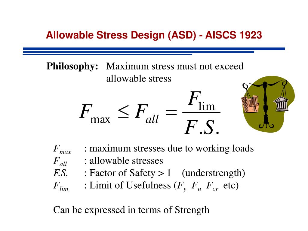
- For ductile materials (like steel or aluminum), failure is typically defined by the onset of permanent deformation, so we use the yield strength ().
- For brittle materials (like cast iron or concrete), which fracture without significant prior deformation, we use the ultimate tensile strength ().
This core principle of Allowable Stress Design (ASD) is summarized perfectly in the following image.
The same logic applies to shear stress ():
3. Application: Designing a Simple Component
Let's see how this is used in practice. A common task is to determine the required size (e.g., diameter, thickness) of a component to safely support a given load. The process is:
- Identify the material's failure strength ( or ) and the required F.S.
- Calculate the allowable stress ().
- Set the actual stress formula (e.g., ) equal to the allowable stress.
- Solve for the required area or other geometric property.
The video resource from Jeff Hanson demonstrates this process clearly.
Mechanics of Materials: Lesson 6 - Factor of Safety Explained, Example Problem
Let's return to the video 'Mechanics of Materials: Lesson 6'. The instructor will now show how to use the factor of safety to calculate the allowable shear stress, and then use that value to find the required diameter for pins in a connection.
Watch from 12:42 to the end of the video (18:12). First, see how he calculates the allowable stress to be used in the problem. Then, follow his calculations for the pin diameters in both single and double shear.
Notice the instructor's terminology: he calls the calculated allowable stress the "actual \tau that we need to use". This is a common way practitioners think about it—it's the new stress limit for the design calculation.
Test your understanding!
A tension rod in an aircraft landing gear assembly must support a load of 90 kN. The rod will be made from a high-strength aluminum alloy with a yield strength of 450 MPa. For this critical application, a factor of safety of 1.8 is required. What is the minimum required diameter for the rod?
Show answer
-
Calculate the allowable stress:
-
Set actual stress equal to allowable stress:
The actual stress is . The area of a circular rod is .
Note: 1 MPa = 1 N/mm² -
Solve for the diameter :
The minimum required diameter is 21.41 mm.
4. Application: Assessing an Existing Design
Let's tie this back to our previous lesson. You calculated the stresses in a pressure vessel, but we didn't determine if it was safe. Now we can.
Example:
Recall the aircraft fuel tank from the last lesson:
- Diameter
- Wall thickness
- Internal pressure
You calculated the maximum stress (the hoop stress) to be .
If the tank is made from an aluminum alloy with a yield strength of , what is the factor of safety against yielding?
Solution:
Using the analysis formula:
The tank has a factor of safety of 9.0, which is very high and indicates a robust design for this operating pressure.
5. Margin of Safety: The Aerospace Standard
In many industries, especially aerospace and defense, engineers often use a closely related term: Margin of Safety (M.S.). The relationship is simple:
A design is considered safe if its Margin of Safety is greater than zero.
Safety Factor, Factor Of Safety, Margin Of Safety, Unity Check
This article from FidelisFEA, 'Safety Factor, Factor Of Safety, Margin Of Safety, Unity Check', provides a clear definition of Margin of Safety and explains its common usage.
Please read the short section titled 'Margin Of Safety (MOS)'.
The Margin of Safety can be interpreted as the percentage of additional capacity the component has. In the pressure tank example above, the F.S. was 9.0.
This means the tank can withstand 800% more stress than the current actual stress before it begins to yield. Using M.S. is standard practice in formal stress reports for aircraft components.
Conclusion
Today you learned how to put stress calculations into a practical design context using the Factor of Safety. This concept is the bedrock of safe and reliable engineering.
Key Takeaways:
- The Factor of Safety (F.S.) is a design margin that accounts for uncertainties in loads, materials, and analysis.
- For designing, you find the allowable stress using .
- For analysis, you find the existing safety factor using .
- For ductile materials, is the yield strength (). For brittle materials, it's the ultimate strength ().
- The Margin of Safety (M.S. = F.S. - 1) is a common standard in the aerospace industry to report if a design is acceptable (M.S. > 0).
Next Lesson Preview:
This lesson concludes our module on fundamental stress and strain concepts. You're now equipped to analyze stresses in axially loaded members, simple connections, and pressure vessels, and to assess their safety.
Next, we will move into Module 3: Torsion and Bending in Beams. These are extremely common and important loading scenarios, especially for aircraft structures like wing spars and fuselage frames. Before we can analyze the stresses caused by bending, we must first understand the geometric properties of the beam's cross-section that determine its resistance to bending. Our next lesson will therefore cover how to calculate centroids and area moments of inertia for common and composite cross-sections.
Can't find a good explanation? Sign up and we'll make it for you
Sign up