
Hello. In the previous lesson, you examined why systems engineering integrates stakeholder needs, technical decisions, and life-cycle concerns rather than treating development as a sequence of isolated specialist tasks. That integration begins with a deceptively simple discipline: being explicit about what is inside the system of interest and what is outside it.
In this lesson, you will identify a system boundary, distinguish direct external interfaces from wider environmental influences, and use a context diagram to communicate the result. These are foundational skills for CSEP-style scenario questions and for building useful SysML models in Cameo: an ambiguous boundary produces ambiguous requirements, architecture, ownership, and verification.
A boundary is an engineering decision
A system boundary delimits the system of interest (SOI): the set of elements, relationships, and behaviors that are being considered as one system for a stated purpose.
It is tempting to treat a boundary as a physical enclosure: the casing around an electronic unit, the fence around a facility, or the body of a vehicle. Physical boundaries sometimes matter, but they are not enough. A system boundary is primarily a purposeful abstraction. It identifies the system whose performance, requirements, architecture, and life-cycle responsibility are currently being analyzed.
For an engineered system, the boundary separates:
- Internal elements: elements considered part of the SOI for the present purpose.
- External entities: people, systems, organizations, or physical phenomena outside the SOI that interact with it.
- Environmental context: external conditions and entities that significantly constrain or influence the SOI.
The boundary is therefore neither arbitrary nor permanent. It depends on the question being asked.
Consider a refrigerated vaccine-delivery service. At one level of analysis, the SOI could be the entire service: dispatch operations, drivers, refrigerated vehicles, temperature monitoring, communications, and operating procedures. At another level, the SOI could be only the onboard temperature-monitoring subsystem. In that second case, the vehicle, driver, dispatch service, and refrigeration unit become external to the monitoring subsystem.
Neither boundary is inherently “correct.” The correct choice is the one that makes the purpose and decision scope clear.
Overview of Design, Lifecycle, and Safety for Computer- ...
Read this NASA technical guide for a precise systems-engineering account of the system of interest, its boundary, and its environment. It provides terminology that is useful for both INCOSE-style reasoning and MBSE scope definition.
In Section 2.1, “System Design,” read the discussion of system purpose and boundary. Focus on the claim that a system achieves its purpose through interactions within itself and with its surroundings. Then continue into Section 2.1.1, “Environment.” Read the three-part environment classification. Notice that relevance, rather than mere physical proximity, determines what belongs in the modeled environment.
A useful boundary statement has four parts:
The system of interest is [named system], which provides [intended service or outcome], during [life-cycle or operational phase], within [scope of responsibility].
For example:
The system of interest is the regional vaccine-delivery service, which transports and hands over viable vaccines to clinics under controlled temperature conditions during routine and surge operations.
That statement is more informative than simply writing “vaccine system” in the center of a diagram. It establishes the intended outcome and begins to expose what must be included.
What does not determine the boundary by itself
Several plausible shortcuts lead to weak system models:
| Shortcut | Why it fails |
|---|---|
| “Everything owned by our organization is inside.” | Ownership, operational responsibility, and technical control often differ. A leased vehicle may be internal; an organizational finance system may be outside the operational SOI. |
| “Everything physically attached is inside.” | A connected external system may remain separately managed and independently developed. |
| “Everything we can influence is inside.” | A system may influence users, regulations, weather exposure, suppliers, and infrastructure without containing them. |
| “Every relevant thing belongs on the diagram.” | A context model becomes unusable when it includes entities with no meaningful effect on the purpose under analysis. |
A practical test is to ask: Does this element need to be designed, configured, integrated, or verified as part of the SOI in order for the stated system purpose to be achieved? If yes, it is a strong candidate for being inside the boundary. If it instead exchanges something with the SOI, it is likely external. If it affects the SOI without participating in a direct exchange, it belongs in the wider context.
Environment: direct interaction versus significant influence
Everything outside the boundary is in the system’s environment in the broad sense. But systems engineering needs a more discriminating view than “inside” and “outside.”
The NASA guide distinguishes three useful categories:
- External systems directly interact with the SOI at its boundary.
- Contextual entities or conditions significantly influence the SOI but are not directly influenced by it.
- The rest of the environment has little or no relevance to the purpose currently being analyzed.
For the vaccine-delivery service, a preliminary classification might look like this:
| Category | Examples | Why it matters |
|---|---|---|
| Internal to the SOI | Dispatch function, drivers, refrigerated vehicles, onboard monitoring, delivery procedures | These elements cooperate to deliver the service and are within the chosen scope. |
| External systems and actors | Warehouse release service, clinic receiving process, telecommunications provider, maintenance provider | The delivery service exchanges vaccines, information, requests, acknowledgements, and support with them. |
| Physical operating environment | Ambient temperature, road conditions, traffic, weather, power availability at sites | These conditions affect travel time, refrigeration load, safety, and service performance. |
| Wider context | Health regulations, funding policy, population geography, disease outbreaks | These influence constraints, demand, and operating priorities. |
| Out of scope for this view | Unrelated municipal services with no effect on delivery | Including them adds visual noise without improving a decision. |
An entity can change category when the scope changes. Suppose the delivery organization decides to design and operate its own maintenance facility. For the delivery-service SOI, that facility might now be internal. For a narrower vehicle-operation SOI, it remains an external enabling system.
This is why a boundary should always be documented with its viewpoint and purpose. A boundary intended to support operational performance analysis may differ from one intended to support procurement, cybersecurity assessment, or subsystem design.
Interfaces: where interaction becomes an engineering obligation
An interface is a point or link through which entities interact. In an engineered system, interfaces are not merely lines on a diagram. They are locations where assumptions must agree.
At a high level, an interface identifies who or what interacts. As definition matures, it describes what is exchanged, under what conditions, and with what constraints.
The most common flows across a boundary are:
- Information: commands, status, sensor data, alarms, acknowledgements, records.
- Matter: vaccines, fuel, consumables, waste, replacement parts.
- Energy: electrical power, heat, cooling capacity, mechanical force.
- Human interaction: decisions, approvals, manual actions, handovers, training.
- Services: maintenance, authentication, location tracking, payment, emergency response.
For the vaccine-delivery service, “communicates with the clinic” is not yet an adequate interface definition. It should be refined into interactions such as:
- dispatch sends an estimated arrival time and delivery manifest;
- the clinic confirms its ability to receive the shipment;
- the driver transfers the vaccine container and chain-of-custody record;
- the clinic acknowledges acceptance or reports a temperature excursion;
- the delivery service records the completed handover.
Each interaction may impose requirements on data content, timing, availability, security, authority, and error handling.
Overview of Design, Lifecycle, and Safety for Computer- ...
Return to the NASA guide for its distinction between an interface as an interaction link and the physical and logical characteristics that make an interaction work.
In Section 2.1.7, “Interfaces,” begin with the interface definition and levels. Then read Section 2.1.7.1 on physical interface attributes, followed by Section 2.1.7.2 on logical interface attributes. Relate these two levels to any familiar device connection: a physical connection alone does not define the data, timing, or behavior exchanged through it.
Physical and logical interface views
A single relationship can have both physical and logical aspects.
For example, a vehicle’s temperature sensor and controller may have:
- a physical interface: connector, pin allocation, supply voltage, cable characteristics, electromagnetic constraints, and mounting;
- a logical interface: measured temperature values, units, update rate, timestamping, fault codes, calibration state, and alarm behavior.
A system can have a perfectly compatible connector and still fail because it interprets temperature values in different units. Conversely, two components can agree on a message format but fail because their electrical signaling or timing is incompatible.
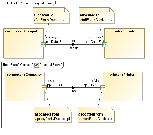
For CSEP reasoning, remember that an interface issue often appears as an integration issue:
- A requirement says an external system must receive an alarm within a specified time.
- One subsystem produces the alarm correctly.
- Another subsystem receives a message but uses an incompatible format or does not handle a communication failure.
- The individual elements may appear correct in isolation, yet the interface fails the system requirement.
A well-defined interface normally addresses, at an appropriate level of detail:
- the interacting entities and their responsibilities;
- the item, service, energy, or material exchanged;
- direction and initiation conditions;
- format, units, protocol, or physical characteristics;
- timing, capacity, and quality constraints;
- safety, security, and failure behavior; and
- verification evidence showing compatibility.
At this stage, do not confuse an interface with a detailed interface control document. The first is the interaction that must be managed; the latter is one possible controlled artifact used to specify it.
Context diagrams: a high-level boundary view
A system context diagram is a high-level visual representation of the SOI, the significant external entities around it, and the interactions crossing its boundary. It is especially valuable early in the life cycle because it turns a vague scope statement into something stakeholders can inspect and challenge.

The central system is not a “hub” that owns every entity around it. The surrounding boxes and actors are deliberately outside its boundary. The value of the diagram lies in revealing questions such as:
- Is a necessary external system missing?
- Has an organization been confused with the system it operates?
- Is an expected input, output, service, or handover absent?
- Have we drawn a dependency without identifying what crosses the interface?
- Are we trying to include internal architecture on a diagram whose purpose is external scope?
How to Use a System Context Diagram in Business Analysis (with example)
Watch “How to Use a System Context Diagram in Business Analysis,” from Bridging the Gap – Resources for Business Analysts. Although the example is software-oriented, the method is directly useful for early systems-engineering scope analysis.
Watch the diagram anatomy to see the central system, surrounding integrated systems, and labeled interaction lines. Then watch the creation method, focusing on stakeholder review as a means of finding missing systems and flows. Apply the method to flows of matter, energy, and human interaction as well as data.
A context diagram is usually an informal scope view, not a complete interface specification. It should remain readable. If it begins to show internal parts, protocols, states, error paths, or hundreds of messages, create additional views rather than overloading the context view.
For an initial Cameo model, you can represent the SOI and external entities as Blocks, parts, actors, or other appropriate model elements. However, the diagram itself should not be mistaken for a complete SysML semantic model merely because it uses SysML-like shapes.
The IBM SysML overview makes this distinction explicit: the context diagram is an informal means of establishing system scope, before the model is refined through requirements and structural views.
Read the Rain Sensing Wiper example from IBM Research for a direct connection between boundary definition, context diagrams, and later SysML structure.
In Section 2, “Context, Requirement and Use Cases,” read the context-diagram discussion. Pay particular attention to the example in which the car electrical system is both an actor and an external system: one real-world entity can play multiple roles relative to the SOI.
Building a defensible context view: a worked approach
Use the following disciplined process for a practical case.
1. State the purpose and choose the SOI
Begin with the service or outcome, not a component list.
For the vaccine case:
Provide scheduled and urgent delivery of viable vaccines from the regional warehouse to designated clinics.
Then declare the SOI:
Regional vaccine-delivery service.
This prevents a common failure mode: placing “refrigerated truck” at the center when the real concern is end-to-end delivery performance.
2. Identify what must be internal
Ask what elements must cooperate to perform the declared service.
For this boundary, include:
- delivery planning and dispatch;
- drivers and delivery procedures;
- refrigerated transport assets;
- onboard temperature monitoring and alerting;
- operational communications used to coordinate delivery;
- records managed as part of the delivery service.
Including people inside a service SOI is legitimate when their roles and procedures are part of the system capability. A purely technical vehicle-subsystem model would choose a different boundary and show the driver externally.
3. Identify direct external entities
Now ask: With whom or what does this SOI exchange something?
Likely external entities include:
- the warehouse release and inventory service;
- receiving clinics;
- a telecommunications service;
- a fleet-maintenance provider, if maintenance is outside the service boundary;
- public road infrastructure and traffic-control systems, where relevant to the operational concept;
- regulators or inspectors, if they directly receive records or conduct audits.
Each entity needs at least one meaningful interaction label. “Clinic” without an identified exchange is only a name, not yet an interface.
4. Add relevant environmental elements
Next, identify conditions that shape required performance:
- ambient temperature and weather;
- traffic conditions and road closures;
- geographic travel distances;
- available power and secure parking;
- regulatory cold-chain limits;
- demand variability during public-health events.
Not every environmental element requires a connector in a simple context diagram. But all significant influences should appear in the operational concept, assumptions, constraints, hazards, or requirements as the model matures.
5. Review the boundary with stakeholders
A context diagram is a hypothesis until reviewed. Warehouse staff may point out that custody transfers before the vehicle leaves the loading bay. Clinic staff may explain that deliveries are accepted only during restricted receiving windows. Maintenance staff may identify a calibration process required for temperature sensors. Each observation can change boundary assumptions, interfaces, requirements, or life-cycle responsibilities.
The review question is not merely, “Is this diagram accurate?” A stronger question is:
“What interaction, condition, or responsibility would cause this service to fail if we omitted it?”
That question exposes hidden dependencies early.
Exam-style distinctions to keep sharp
When reading a scenario, separate the terms precisely.
- Boundary: the conceptual limit of the selected SOI.
- Internal element: an element within that limit.
- External system: a separate system that directly interacts across the boundary.
- Environmental element: an external condition or entity that affects the SOI; it may or may not directly interface with it.
- Interface: the interaction link and its defined exchange across a boundary or between internal elements.
- Context diagram: a high-level representation of the SOI, its environment, and its principal external interactions.
Watch for these distractors:
- Treating every nearby or relevant system as part of the SOI.
- Treating every environmental influence as a direct information interface.
- Defining an interface only by its physical connector while ignoring information, behavior, timing, or responsibility.
- Using an organizational boundary as though it automatically defines a system boundary.
- Filling a context diagram with internal subsystem decomposition.
Key takeaways
A system boundary is a purpose-dependent engineering decision that identifies what belongs to the system of interest for a defined analysis or life-cycle concern. It is not determined solely by physical enclosure, ownership, or organizational reporting lines.
External systems interact directly with the SOI through interfaces. The wider environment includes physical conditions, regulations, and contextual entities that influence system performance and constraints. Relevance to the system purpose determines what must be represented.
A context diagram is a concise, high-level tool for communicating the boundary, major external entities, and the flows or services crossing the boundary. It should clarify scope rather than attempt to document internal architecture or every interface detail.
Next, you will extend this boundary view by examining hierarchy, interactions, interdependencies, and emergent behavior—the reasons a collection of individually sound elements may still fail at the system level.
Can't find a good explanation? Sign up and we'll make it for you
Sign up