Hello Alex,
Welcome back. In our last lesson, we explored the physical structure and fundamental operating principles of MOSFETs, contrasting the "normally off" enhancement-mode with the "normally on" depletion-mode devices. We conceptually defined the operating regions: cutoff, triode (or ohmic), and saturation.
Today, we will quantify these concepts by diving into the MOSFET's Current-Voltage (I-V) characteristics. We'll analyze the graphs and equations that describe the drain current () as a function of the gate-source voltage () and drain-source voltage (). Mastering these relationships is essential for using a MOSFET as either an amplifier or a switch.
Learning Outcome: MOSFET I-V Characteristics: Cutoff, Triode, and Saturation Regions.
Approximate time to complete: 55 minutes.
1. Understanding the MOSFET's Operating Regions
As a voltage-controlled device, a MOSFET's drain current () is governed by two key voltages:
- Gate-Source Voltage (): This is the primary control input. It determines whether a channel exists and how conductive it is.
- Drain-Source Voltage (): This voltage pushes the charge carriers through the channel (if one exists), creating the drain current.
The interplay between and defines the transistor's region of operation. We will focus on the N-channel enhancement-mode MOSFET, as it is the most common type and its principles are easily adapted to others.
Let's begin by examining the output characteristics, where we plot versus for different, fixed values of .
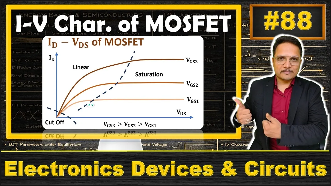
This video provides an excellent step-by-step walkthrough connecting the physical phenomena inside the MOSFET to the resulting I-V curves.
2. The Output Characteristics: vs.
Imagine we have an N-channel E-MOSFET in a circuit where we can independently set and sweep from zero upwards.
A. Cutoff Region ()
First, let's set to a value less than the threshold voltage ().
- Watch: Introduction and Cutoff Region (00:00 - 01:08) in the video above.
As you recall from our last lesson, if is not sufficient to create the inversion layer, no channel connects the source and drain. Therefore, no matter what value we apply for , the drain current remains zero. On the I-V plot, this corresponds to the horizontal axis.
- Condition:
- Behavior: The device is OFF.
- Result:
B. Triode (or Linear) Region ( and small )
Now, let's apply a gate voltage that is greater than . A conductive channel is formed.
- Watch: The Linear (Triode) Region (01:08 - 04:10).
As we begin to increase from zero, a current starts to flow. For small values of , the channel behaves much like a simple resistor. The current increases in a nearly linear fashion with . Because of this resistor-like behavior, the triode region is also called the ohmic region.
However, as increases, the voltage drop along the channel becomes significant. The potential difference between the gate and the channel is largest near the source () and smallest near the drain (). This causes the channel to become tapered, or narrower, at the drain end. This narrowing increases the channel's resistance, causing the I-V curve to bend and become less steep.
C. Saturation Region ( and large )
What happens if we keep increasing ?
- Watch: Saturation and Pinch-Off (04:10 - 08:46).
Eventually, becomes large enough that the voltage between the gate and the drain end of the channel () drops to the threshold voltage, . At this point, the channel is "pinched off" at the drain.
The value of where this occurs is called the saturation voltage, . This happens when:
Once exceeds , the pinch-off point forms. Any further increase in is simply dropped across this pinched-off depletion region. The current flowing through the channel is now "saturated" and, ideally, becomes constant, independent of further increases in . The MOSFET now behaves like a constant current source, with the value of that current controlled by .
A Family of Curves
If we repeat this process for several different (and higher) values of , we generate a family of curves.
- Watch: The Impact of VGS (08:46 - 11:09).
A higher creates a more conductive channel (lower resistance) from the start. This results in:
- A steeper initial slope in the triode region.
- A higher saturation current .
- A higher drain-source voltage required to enter saturation.
The resulting plot looks like this:
[MOSFET I-V curves](IMAGE_ID:
/home/runner/work/teaching-assistant/teaching-assistant/courses/Radioelectronics_fundamentals_then_advanced_math/lessons/5_6_MOSFET_IV_Characteristics_Cutoff_Triode_and_Saturation_Regions/iv_curves.png
)
A family of I-V curves for an N-channel enhancement MOSFET. Each curve corresponds to a fixed V_GS. The dashed parabola marks the boundary between the triode and saturation regions.
3. The Governing Equations
Now, let's attach the mathematical models to these regions. The equations involve process parameters () and device geometry (the width-to-length ratio, ).
- is the process transconductance parameter. It depends on electron mobility () and the gate oxide capacitance per unit area ().
- is the aspect ratio of the transistor, a key design parameter.
The video below clearly presents these equations.
- Watch: from 11:09 to 14:05.
Here is a summary of the conditions and the resulting drain current equations for an N-channel E-MOSFET:
| Region | Voltage Conditions | Drain Current Equation () |
|---|---|---|
| Cutoff | ||
| Triode | , | |
| Saturation | , |
Note that the saturation current equation is derived by substituting the boundary condition into the triode equation.
4. Transfer Characteristics and Channel Length Modulation
The I-V curves we've seen so far are ideal. A real MOSFET has a second-order effect that you should be aware of, which is particularly relevant in analog circuit design.
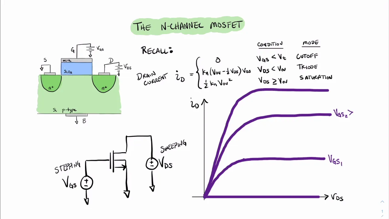
- Watch: Channel Length Modulation and Early Voltage (07:42 - 10:55) in the video above.
In reality, the saturation region is not perfectly flat. As increases beyond , the length of the pinched-off region near the drain actually grows, which slightly shortens the effective length, , of the conductive channel. Since is in the denominator of the current equation, a smaller effective results in a slightly larger drain current. This phenomenon is called channel-length modulation.
To model this, we modify the saturation equation with a parameter, , the channel-length modulation parameter:
This adds a linear dependence on in the saturation region, giving the curves a slight upward slope. If you extrapolate these sloped lines backward, they all intersect the voltage axis at a single point, . This is the Early Voltage, a concept you'll remember from BJTs. The relationship is . For many digital applications this effect is ignored, but for analog amplifiers, it's the source of the transistor's finite output resistance.
Conclusion
In this lesson, we put mathematical rigor behind the MOSFET's operating regions. You can now look at a MOSFET's terminal voltages and determine its state and the resulting current.
Key Takeaways:
- Cutoff Region: The transistor is OFF () when .
- Triode Region: The transistor acts like a voltage-controlled resistor. This occurs when and is small ().
- Saturation Region: The transistor acts like a voltage-controlled current source. This occurs when and is large enough to pinch off the channel ().
- The transition between triode and saturation is defined by the condition .
- Channel-length modulation is a real-world effect that gives the saturation curves a slight positive slope, which is modeled by the parameter or the Early Voltage .
Now that we have a firm grasp of these I-V characteristics, we are ready to apply them. In our next lesson, "The MOSFET as a Switch in Digital Logic," we will see how the sharp contrast between the cutoff (OFF) and triode (ON) regions makes the MOSFET the perfect building block for the logic gates that power our digital world.