
In our last session, we diagnosed the common defects in stamping—springback, wrinkling, and tearing—and looked at the process controls used to fight them. This is a reactive approach, essential for any plant engineer. Today, we shift to a proactive stance. As a design engineer, your primary responsibility is to design parts that are inherently manufacturable, minimizing the need for extensive process correction later.
This lesson focuses on the "golden rules" of sheet metal design. These aren't arbitrary guidelines; they are fundamental principles derived from material physics and the practical constraints of stamping dies. Mastering them is non-negotiable for producing cost-effective, high-quality automotive components. We will cover three core areas:
- Bend radii, with a special focus on High-Strength Steel (HSS).
- Placement of features like holes and slots to prevent deformation.
- Minimum flange and leg lengths required for stable forming.
By the end of this lesson, you will be able to apply these rules to critique a design for manufacturability.
The Foundation: Why Design Rules Matter
Every rule we discuss today is a direct countermeasure to the defects we analyzed previously. A radius that's too sharp concentrates stress and causes tearing. A hole too close to a bend distorts because it's in a zone of plastic flow. A flange that's too short can't be properly formed, leading to inconsistent angles and springback. Your MEng background gives you the theoretical understanding of stress, strain, and plastic deformation; these rules are the applied, practical embodiment of that theory on the production floor.
Rule 1: Internal Bend Radius ()
The internal bend radius is arguably the most critical parameter in sheet metal design. It directly influences the risk of cracking and the amount of springback.
To start, let's watch a segment that introduces the general rule of thumb for bend radii and other essential DFM tips.
Design Tips for Sheet Metal Bending
This video from Xometry Europe provides a concise overview of several key design-for-manufacturability (DFM) rules. We will refer back to it for other topics, but for now, focus on the fundamental concepts of bend radius and feature placement.
Please watch the following segments: Bend radius: Pay attention to the baseline recommendation for minimum bend radius and the cost benefit of keeping radii consistent. Bend reliefs: Understand the purpose and basic dimensioning of a relief cut. Holes and slots: Note the recommended clearances for placing features near a bend.
As the video states, the standard industry guideline is:
The internal bend radius () should be at least equal to the material thickness ().
A radius smaller than this creates a severe stress concentration on the outer surface of the bend, significantly increasing the risk of cracking—the "tearing" defect we discussed. In CATIA's Sheet Metal Design workbench, this internal radius is a fundamental parameter you define when creating a flange or bend feature. Getting this value right from the start is critical.
Special Considerations for High-Strength Steel (HSS)
The rule is a good starting point for mild steels, but HSS behaves differently. As we learned, HSS has lower ductility (less total elongation) and exhibits significantly more springback. This creates a design conflict:
- To Minimize Springback: You want a smaller, sharper bend radius. This "sets" the material more permanently.
- To Prevent Cracking: You need a larger radius to accommodate the lower ductility of HSS.
Navigating this trade-off is a core challenge of BIW design. The "High Strength Steel Stamping Design Manual" provides guidance from the Auto/Steel Partnership on this exact issue.
[PDF] High Strength Steel Stamping Design Manual
This manual is an industry-standard guide. We'll consult it to understand how the rules change for high-performance materials. You'll see that practical engineering often involves balancing competing requirements.
Read the following two excerpts carefully: Section 3, Page 30, "Form and Flange Dies": Find the paragraph starting "The punch radius also affects springback." Note the recommendation for punch radius (which forms the part's internal radius) and the specified overbend allowance for HSS. Section 5, Page 52, "Form and Flange Dies": This section on die tryout reinforces the same rules. Read the first paragraph under this heading. It gives you an idea of what a process engineer looks for.
From these sections, we can establish the golden rule for HSS bend radii:
- For HSS, the punch radius (and thus the part's internal bend radius) should be minimized to reduce springback, typically 1 to 2 times the metal thickness (1T to 2T).
- However, the radius must be large enough to prevent cracking. The exact value depends on the specific grade of steel. A case study in the same manual (Section 6, Page 62) describes starting with a radius of less than 1T and adjusting based on tryout results.
- Crucially, the die must compensate for springback with an overbend of 6 degrees or more, compared to the 3 degrees typical for mild steel.
Question for you: A design for a BIW A-pillar reinforcement, made from 1.5 mm DP980 steel, specifies a 1.0 mm internal bend radius. Based on the HSS guidelines, what would be your immediate concern during a design review?
Answer
My immediate concern would be the high risk of cracking. A 1.0 mm radius on a 1.5 mm thick HSS part is only 0.67T. While a sharp radius helps fight springback, DP980 is a very high-strength, low-ductility material. This radius is likely too aggressive and falls below the recommended 1T-2T starting range, risking material failure during forming. I would flag this for a formability simulation and discussion with the stamping process engineer.Rule 2: Feature Placement and Bend Relief
Placing holes, slots, or other cutouts too close to a bend line will cause them to deform. The material near the bend is undergoing plastic deformation, and any feature within that zone will be distorted.
The video from Xometry provided the basic rules. Let's look at a more comprehensive guide to solidify these numbers.

The common rules of thumb, as shown in the image and supporting resources, are:
- Holes to Bend: The distance from the edge of a hole to the start of the bend (the tangent line) should be at least 2.5 times the material thickness ().
- Slots to Bend: Slots are more prone to deformation and require more clearance, typically at least 4 times the material thickness ().
- Bend Relief: When a bend must terminate near an edge, tearing will occur unless a relief cut is provided. The relief allows the material to flow without stretching.
- Relief Width: Should be at least .
- Relief Depth (Length): Should be equal to or greater than the internal bend radius ().
This is an area where early DFM pays huge dividends. Moving a hole by a few millimeters in the CAD model can prevent thousands of dollars in tooling rework and scrap parts.
Rule 3: Minimum Flange Length
A flange is the bent leg of a sheet metal part. For a press brake to form a clean, accurate bend, the die must have enough material to grip. If the flange is too short, it can slip in the die or fail to form correctly.
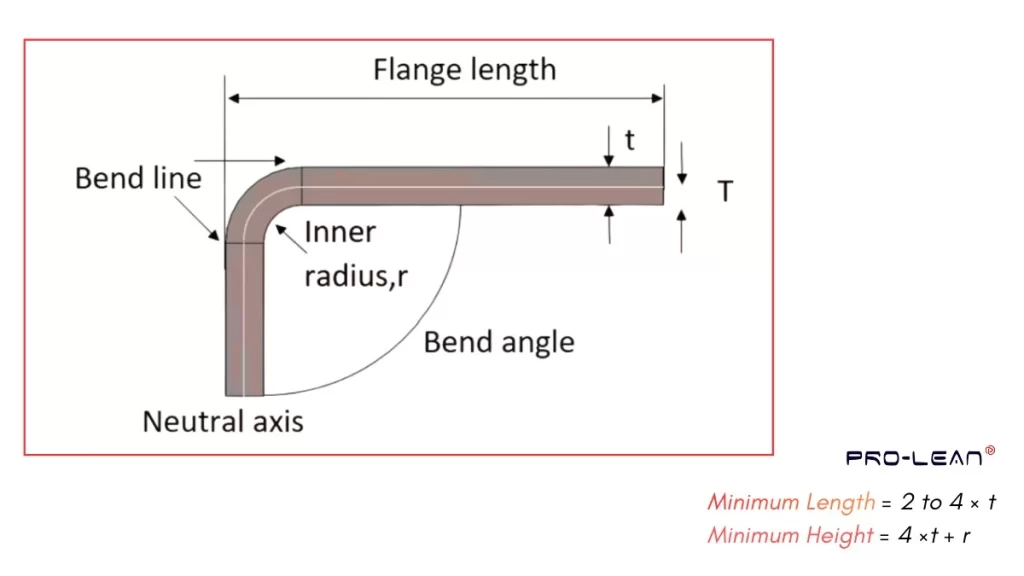
The general rule is straightforward:
The minimum flange length should be at least 4 times the material thickness ().
This rule is a direct function of the tooling used. In "air bending," the sheet is supported by two points on the lower V-die. The flange must be long enough to span across the V-die opening and make stable contact.
For a more detailed breakdown, the Xometry Pro article provides excellent tables.
Sheet Metal Bending Design Tips | Xometry Pro
This article is a fantastic DFM reference. We'll focus on the sections related to flange length and the summary table.
Please review the following: "Quick Reference Design Table for Bending": Find the rows for Minimum Flange Length and Minimum Leg Length. Note the baseline recommendations. "Minimum Bendable Lengths: Legs and Flanges": Read this section and examine the tables for Steel/Aluminum and Stainless Steel. Notice how the minimum length increases with thickness.
The tables in this resource provide specific, actionable values that you would use in a real design project. For example, a 3.0 mm thick steel part requires a flange of at least 12.5 mm for a 90° bend. Designing a flange shorter than this is asking for manufacturing problems.
Conclusion
In this lesson, we have established the foundational design rules that prevent the most common stamping defects. These are not mere suggestions; they are the language of manufacturability in sheet metal design.
Key Takeaways:
- Bend Radius: The default is . For HSS, it's a trade-off: use a small radius (1T-2T) to combat springback but ensure it's not so small that it causes cracking. Always account for increased overbend in the tooling (6°+).
- Feature Placement: Keep holes at least and slots at least away from bends to prevent distortion. Use bend reliefs where bends are close to edges.
- Flange Length: Ensure flanges are at least long to allow for proper engagement with forming tools. Refer to tooling and material-specific tables for precise values.
Adhering to these rules at the CAD stage is the most effective way to ensure a smooth transition from design to production.
In our next lesson, we will get into the mathematics behind the flat pattern. You will learn how to calculate a flat pattern from a 3D model using the concepts of K-factor and bend allowance, which are the numerical basis for how software like CATIA unfolds your designs.
Can't find a good explanation? Sign up and we'll make it for you
Sign up