
Welcome back. You now have two inputs that should shape the architecture: a prioritized pilot journey and a set of quality-attribute scenarios. The pilot must ingest tenant-scoped Microsoft Entra ID sign-in events, detect impossible travel, and let authorized analysts investigate and close alerts. Its credibility depends on timely detection, tenant isolation, recovery from processing failure, and visible integration health.
This lesson turns that material into a system-context diagram. At principal level, this is the first diagram that establishes a shared answer to: What system are we building, who uses it, what does it depend on, and where does trust change? It deliberately does not reveal services, databases, queues, or cloud topology yet.
Context is a level of zoom, not a vague “high-level diagram”
A system-context diagram treats the system under design as a single black box. It shows:
- the system’s name and business purpose;
- human roles that interact with it;
- external software systems and data sources;
- meaningful, labeled relationships;
- the system scope boundary and the trust boundaries relevant to those relationships.
The distinction from the next diagram types matters.
| Diagram | Primary question | What it contains | What it intentionally omits |
|---|---|---|---|
| System context | What surrounds the system, and what is in scope? | People, external systems, high-level interactions, trust zones | Internal applications, databases, deployment details |
| Container diagram | What major technical building blocks make up our system? | Web applications, APIs, workers, data stores, message brokers | Class-level implementation |
| Threat-model DFD | How does sensitive data move, transform, and cross trust boundaries? | Processes, data stores, external entities, explicit data flows | Broad product storytelling and every incidental dependency |
The C4 model is useful here because it gives each diagram a distinct purpose rather than allowing one sprawling boxes-and-arrows drawing to answer every question poorly.
The C4 Model – Misconceptions, Misuses & Mistakes • Simon Brown • GOTO 2024
Watch “The C4 Model – Misconceptions, Misuses & Mistakes” from GOTO Conferences for a compact explanation of architecture-diagram zoom levels and the questions that define a system-context view.
Watch the C4 overview for the Context, Containers, Components, and Code levels. Then watch context questions and note the questions about scope, users, internal capabilities, and external integrations. Those questions are your construction checklist.
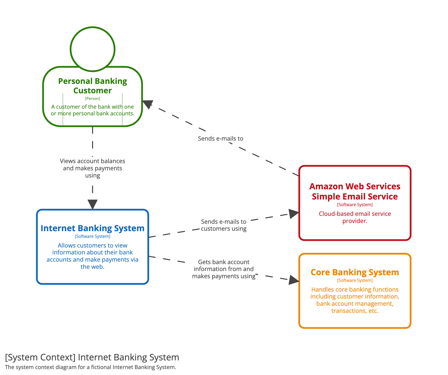
The banking example is deliberately sparse. It does not reveal the banking system’s database, frontend framework, network layout, or internal services. That restraint is what lets product, security, operations, and engineering stakeholders agree on scope before debating implementation.
Create architecture design diagrams - Azure
Read Microsoft’s guidance for the definition of a context diagram and a concise set of practices that prevent diagrams from becoming ambiguous or overloaded.
In “Diagramming practices,” read the clarity guidance, focusing on labels, consistent relationship direction, accuracy, and progressive disclosure. Then, in “Context diagram,” read the context-diagram definition. Apply its “single black box” rule strictly in the diagram you create below.
A practical rule follows:
If a viewer can infer your internal service decomposition from the system-context diagram, you have probably crossed into container-diagram territory.
Scope boundaries and trust boundaries answer different questions
These two boundaries are often drawn with the same rectangle, which causes confusion.
The system scope boundary
The system boundary answers an ownership and responsibility question:
What software capability are we designing and accountable for?
For this pilot, the boundary is the Tenant Behavioral Detection Platform. It owns the product capability of accepting telemetry, evaluating the approved detection logic, and serving tenant-scoped investigation workflows.
The following remain outside that boundary:
- a tenant’s Microsoft Entra ID environment;
- the pre-existing corporate identity service;
- the browsers or API clients used by tenant administrators and analysts;
- the platform operations team, which is a user of the platform rather than an internal implementation component.
An external system may be managed by the same company, deployed in the same cloud, or accessed through a private network and still be outside the system boundary. The deciding issue is whether it is part of the workload you are currently describing.
A trust boundary
A trust boundary marks a point at which the assurances you can make about an actor, process, data item, or privilege level change.
A trust boundary is not simply:
- an internet boundary;
- a virtual network boundary;
- an encryption boundary;
- a line between two boxes;
- a claim that everything on one side is “safe.”
A browser used by an authenticated analyst still sends client-controlled input. A federated identity provider may issue valid tokens, but the platform must determine whether the issuer, audience, signature, expiry, and tenant claims are acceptable. A tenant telemetry source may be legitimate but can still provide malformed, delayed, duplicated, or unexpectedly high-volume events.
For this course’s pilot, the context diagram should make four trust changes visible:
| Boundary crossing | Why trust changes | Architecture concern it exposes |
|---|---|---|
| Tenant user client to platform | Requests, parameters, and bearer credentials arrive from outside the platform | Authentication, authorization, input handling, tenant scoping |
| Corporate identity service to platform | Identity assertions are produced by a separately managed security domain | Issuer trust, signing-key validation, claim validation, federation availability |
| Tenant Entra ID source to platform | Telemetry originates outside the platform and may be delayed, malformed, replayed, or absent | Source authentication, event provenance, ingestion protection, source-health monitoring |
| Platform operator to platform | Operator actions have a wider blast radius than ordinary tenant actions | Privileged access, auditability, separation of duties |
The key security invariant from the prior lesson also needs a visible home:
Tenant isolation is a logical authorization and data-access boundary, not necessarily a separate network boundary per tenant.
At context level, show that the platform serves multiple tenants and all tenant-facing interactions are tenant-scoped. Later diagrams will show where the tenant context is enforced in APIs, jobs, queries, and storage.
Construct the pilot’s system context
Start with a one-sentence statement of scope. This keeps the diagram from drifting into generic “security platform” claims.
Tenant Behavioral Detection Platform: A multi-tenant pilot that receives tenant sign-in audit events, detects approved impossible-travel behavior, and enables authorized analysts to investigate and close tenant-scoped alerts.
Next, inventory the entities implied by the requirements already established.
1. Identify distinct human roles
Do not use one generic “User” box when roles differ in goals or privilege.
| Person | Interaction with the pilot | Why it is distinct |
|---|---|---|
| Tenant administrator | Configures a tenant data source and maintains its authorization | Controls integration setup, not alert investigation |
| SOC analyst | Views evidence, investigates alerts, and records dispositions | Needs access to tenant-scoped alert data |
| Platform operator | Observes source health and incident state | Has operational visibility that must be treated as privileged |
The platform operator is inferred from the operational scenario about a silent source. It should be marked as a design assumption if the pilot has no dedicated operations role yet. The point is not to invent a team; it is to expose who must diagnose a telemetry failure.
2. Identify external software systems
An external system belongs on the diagram when the platform has a meaningful integration, dependency, or data exchange with it.
| External system | Relationship to the pilot | Known or assumed |
|---|---|---|
| Microsoft Entra ID audit source | Provides tenant-scoped sign-in audit events | Known source system; transport is not yet specified |
| Corporate identity service | Establishes workforce identity for administrators and analysts | Known dependency from the product brief |
| Tenant browser or API client | Presents the tenant administrator and analyst interface | Conceptually present, but normally represented through the person unless client software itself is architecturally important |
Notice the restraint: there is no queue, database, rules engine, notification provider, Kubernetes cluster, or cloud account. None is needed to answer the context question.
3. Label relationships by meaningful action or data
Labels should express a business or security-relevant exchange, not generic phrases such as “connects to” or “uses API.”
Good labels for this pilot include:
- “configures source and connector authorization”
- “views evidence and records alert dispositions”
- “tenant-scoped sign-in audit events”
- “identity assertions and signing metadata”
- “views source health and incident state”
At context level, an arrow indicates the primary initiator or the primary direction of meaningful data. It is not a protocol trace. Exact OAuth redirects, webhook acknowledgements, polling, retries, and response payloads belong in later sequence diagrams or threat-model DFDs.
4. Draw the black box and trust zones
Here is a first-pass context diagram for the pilot. The labels “trust zone” identify a change in control, privilege, or assurance; they do not claim that everything inside a zone is automatically trusted.
This diagram is useful because it makes several consequential facts reviewable:
- The platform’s user-facing surface is multi-role, not a single generic portal.
- Microsoft Entra ID is an external source whose delivery method remains unresolved.
- Federated identity is a dependency rather than an implementation detail hidden inside the platform.
- Operational health is part of the product boundary, supporting the earlier silent-source scenario.
- The pilot accepts data and identities from separate security domains.
- The core requirement is tenant-scoped alert investigation, not merely event ingestion.
Record uncertainty instead of concealing it
A diagram is not a contract merely because it looks polished. Add assumptions adjacent to it or in a linked design note.
For this pilot, record at least:
- Identity assumption: The existing corporate identity service is external to the platform and can provide workforce authentication compatible with the pilot’s access model.
- Telemetry assumption: Microsoft Entra ID can provide the sign-in audit data needed for impossible-travel detection.
- Transport decision pending: The source may deliver events or the platform may collect them; the system context shows the semantic flow without prematurely choosing either mechanism.
- Tenant invariant: Administrators and analysts can access only data authorized for their tenant; platform support access, if needed, requires a separately defined privileged workflow.
- Operational-role assumption: A platform operator can inspect integration health without gaining unrestricted tenant evidence access.
This is architecture framing, not indecision. Each assumption can later become a discovery task, security requirement, or architecture decision.
Use the context diagram to prepare threat modeling, but do not turn it into a DFD
A context diagram should expose enough to decide where deeper security analysis is needed. It should not itself pretend to enumerate every data store and security control.
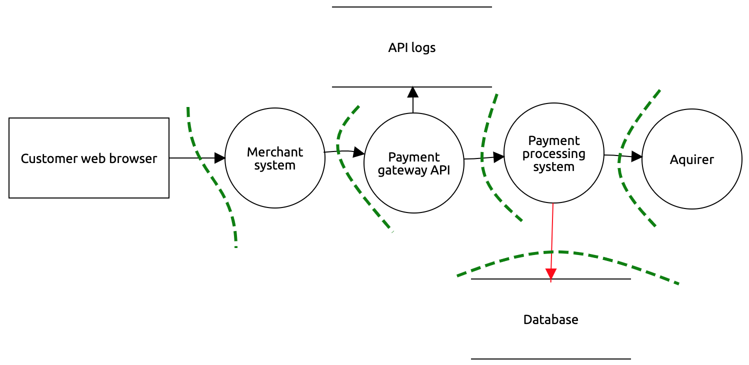
The payment diagram is valuable for a different reason: it exposes internal processes, data stores, and individual flows that can be examined for attack paths. For example, a payment gateway, payment processor, API logs, and database are visible as separate elements.
For the behavioral-detection pilot, a future DFD could expand only the critical path:
- Entra audit-event collection or receipt;
- event acceptance and validation;
- tenant-context propagation;
- detection evaluation;
- alert evidence persistence;
- analyst retrieval and disposition;
- audit logging.
The OWASP guidance explains why this additional detail matters for threat modeling.
Threat Modeling - OWASP Cheat Sheet Series
Read OWASP’s concise explanation of system modeling and why data-flow diagrams are the appropriate next artifact once a system context is agreed.
In “Addressing Each Question” under “System Modeling,” read the discussion beginning with the paragraph that introduces DFDs and continue through the DFD scope. Focus on the distinction between external entities, processes, data stores, flows, and trust boundaries. Do not add those internal DFD elements to the context diagram yet.
A useful handoff statement is:
The system-context diagram identifies which external relationships and trust changes deserve analysis. The DFD identifies how data moves through the system across those boundaries.
A practical review method for your diagram
Treat the diagram as a review artifact rather than a decorative deliverable. A 10-minute walkthrough with product, security, and operations stakeholders can reveal missing dependencies early.
Context-diagram quality gate
Before considering the diagram complete, verify that it meets these criteria:
- Clear system of interest: The system has one name, one explicit boundary, and a short purpose statement.
- No internal leakage: There are no databases, queues, microservices, modules, cloud subnets, or programming languages inside the context view.
- Roles are meaningful: Distinct human roles differ in permission, goal, or risk.
- External systems are real: Every system has a known integration, dependency, or data exchange; speculative systems are labeled as assumptions.
- Relationships are labeled: Each line answers what is exchanged or what action is performed.
- Direction is consistent: Relationship direction reflects the initiating party or primary semantic data flow.
- Trust changes are explicit: The diagram identifies externally controlled, federated, tenant-operated, and privileged operational zones.
- Tenant scope is visible: The platform is explicitly multi-tenant, and tenant-scoped data is named where relevant.
- Unknowns are visible: Transport, ownership, retention, and support-access uncertainties are not buried.
- Metadata exists: Store a title, version, author, last updated date, and a link to the requirements or architecture brief alongside the diagram source.
Short studio activity
Create a version of the pilot context diagram in your preferred diagram-as-code or diagramming tool and store its source with the architecture brief. Keep the platform as a single black box. Add the three stated roles, the two known external systems, labeled relationships, and the five assumptions listed above.
Then conduct a boundary-focused review of the draft:
- Check whether every incoming relationship has an identified trust change.
- Confirm that “tenant-scoped” appears where it matters, rather than relying on tenant isolation being implied.
- Ask product and integration owners to resolve whether Entra telemetry is delivered to the platform or collected by it.
- Ask security to confirm whether the corporate identity service and Entra source are separate trust domains in the intended deployment.
- Promote unresolved assumptions into tracked discovery items before designing internal containers.
Key takeaways
A system-context diagram is a deliberately constrained architecture view. It presents the system as one black box and establishes:
- the product’s scope and purpose;
- the people who interact with it;
- the external systems and data sources it depends on;
- the meaningful high-level interactions;
- the trust boundaries that require deeper security analysis.
For the behavioral-detection pilot, the critical external relationships are tenant administrators, SOC analysts, platform operators, the corporate identity service, and Microsoft Entra ID audit data. The most important boundary concerns are untrusted client input, federated identity, externally sourced telemetry, privileged operations, and tenant-scoped access.
Next, you will zoom one level inward and construct a container-level diagram for the secure backend platform. That view will decompose this black box into the major deployable applications and data stores needed to satisfy the functional and quality requirements already established.
Can't find a good explanation? Sign up and we'll make it for you
Sign up