
Welcome to the final session of our intensive design and manufacturing course. We have navigated the entire engineering change process for the BIW bracket, starting from interpreting the ECO, analyzing its impact on manufacturing and assembly, updating the DFMEA to formally assess risk, and finally, creating a DVP&R to validate our design changes. Today, we complete the cycle by creating the official documentation that releases this change to the organization.
Our final learning outcome is to produce updated 2D drawings with revised GD&T and document the ECO in a PLM-style change notice. This is where we package all our engineering work into a formal, traceable, and legally binding set of documents. This final step ensures that what you designed is what gets built, inspected, and shipped.
1. The Engineering Drawing: The Source of Truth
The 3D model is essential for design and analysis, but in the automotive world, the 2D drawing remains the contractual document. It is the ultimate source of truth for manufacturing, quality control, and suppliers. When we implement an ECO, the drawing must be meticulously updated to reflect the change.
A critical part of this update is not just changing the geometry, but also documenting the change itself. This is done in the revision block of the drawing.
Engineering Change Order (ECO) Software - Sibe PDM
This article from Sibe PDM provides excellent context on the formal change management process. We'll be using its structure to build our change notice later. For now, focus on the standards that govern these processes.
First, read the bullet point that mentions ASME Y14.35 in the section "Why disciplined ECO management matters." Then, jump to the section "A handful of best practices to get started" and read the first point, "Define your change taxonomy," which also references ASME Y14.35.
The resource highlights ASME Y14.35, "Revision of Engineering Drawings and Associated Documents." This standard dictates how to properly manage drawing revisions. Key elements include:
- Revision Letter: Each time a drawing is formally released, its revision letter is incremented (e.g., A, B, C). Our original drawing was Rev A; the updated drawing will be Rev B.
- Revision Block: A table on the drawing that logs each revision. It includes the revision letter, a description of the change, the date, and the approver's name or initials.
- Revision Zone: A marker on the drawing field indicating the location of the change (e.g., C4).
For our bracket, the drawing update would involve:
- Changing the drawing views to show the new gusset.
- Adding "B" to the revision block with the description "Added reinforcing gusset per ECO-BIW-BRKT-001" and today's date.
- Updating the GD&T.
Revising the GD&T
The most critical technical update to the drawing is ensuring the GD&T is complete and correct for the new geometry. The original drawing would have had controls for the holes and flanges. Now, we must add a control for the new gusset.
A profile of a surface tolerance is the ideal tool for this. It defines a 3D tolerance zone that controls the form, orientation, and location of a surface simultaneously. We will apply a profile tolerance to the gusset, referencing our existing datum reference frame (A, B, C).

The feature control frame for our new gusset might look like this:
| профиль поверхности | 0.8 | A | B | C |
|---|
This frame communicates to the inspector: "The entire surface of this gusset must lie within two parallel surfaces 0.8mm apart, which are perfectly oriented and located with respect to datums A, B, and C." This single callout ensures the gusset is in the right place and has the right shape.
2. The PLM Change Notice: Authorizing the Change
The updated drawing is the "what," but the PLM system is where we document the "who," "why," and "when." The Engineering Change Notice (ECN) is the digital object in the PLM system that bundles all information about the change.
Engineering Change Order (ECO) Software - Sibe PDM
Let's return to the Sibe PDM article to understand the structure of the formal change document.
Read the sections: "What an ECO actually is..." to understand the ECR/ECO/ECN terminology. "The ECO data model that scales" to see the list of attributes that make up a robust change object. "A reference ECO workflow..." to see how the document moves from creation to release.
The article provides a clear blueprint for the data required to document a change. This isn't just bureaucratic paperwork; every field serves a purpose for traceability, cost analysis, and production planning.
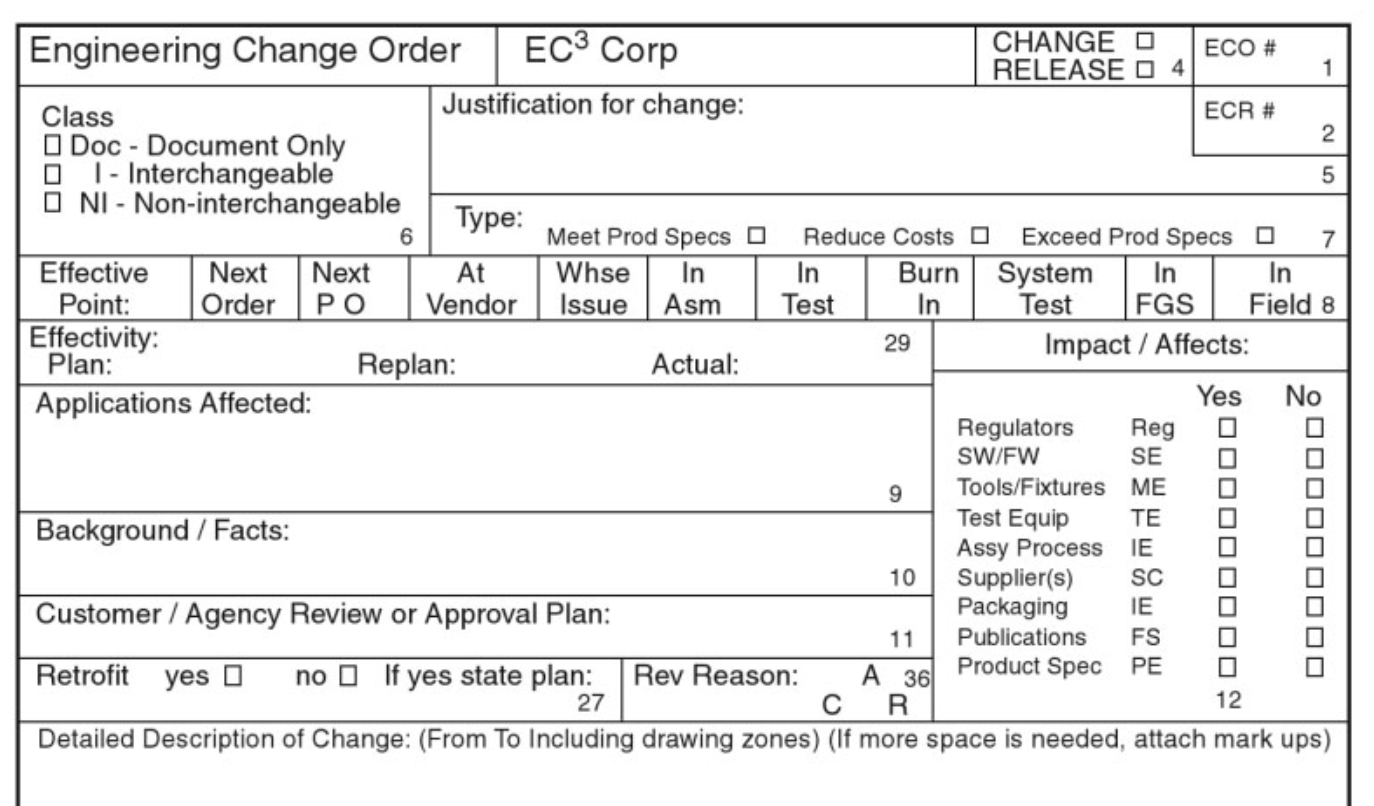
3. Your Task: Create the Engineering Change Notice
You are now at the final approval gate for the BIW bracket change. You have completed all the engineering analysis. Your final task is to create the formal ECN in the PLM system to authorize the release of the updated design.
Using the knowledge from the resources and our work this week, fill out the key fields in the ECN template below for our bracket ECO. Be concise and professional, as this document will be reviewed by all departments from manufacturing to finance.
Engineering Change Notice (ECN) Template
| Field | Your Input |
|---|---|
| ECN Number | ECN-BIW-BRKT-001 (Auto-generated by PLM) |
| Title | |
| Originating ECO | ECO-BIW-BRKT-001 |
| Reason for Change | |
| Description of Change | |
| Affected Items | Part: PN 987-654321-LH, New Rev: C Drawing: DWG 987-654321-LH, New Rev: B |
| Attachments | 1. DWG 987-654321-LH_RevB.pdf 2. MDL 987-654321-LH_RevC.step 3. (Add two more critical documents from our previous lessons) |
| Effectivity |
Click here to see my proposed ECN entries.
Here is how I would complete the Engineering Change Notice. Your phrasing may vary, but the content should capture these key points.
| Field | My Input |
|---|---|
| ECN Number | ECN-BIW-BRKT-001 (Auto-generated by PLM) |
| Title | Add Reinforcing Gusset to BIW Mounting Bracket |
| Originating ECO | ECO-BIW-BRKT-001 |
| Reason for Change | Improve component stiffness to meet NVH (Noise, Vibration, Harshness) performance target identified in vehicle-level testing. |
| Description of Change | Added a 15mm x 40mm reinforcing gusset to the main flange. Updated 2D drawing to Rev B with profile of surface tolerance to control new feature. No change to material (DP600) or gauge (1.8mm). |
| Affected Items | Part: PN 987-654321-LH, New Rev: C Drawing: DWG 987-654321-LH, New Rev: B |
| Attachments | 1. DWG 987-654321-LH_RevB.pdf 2. MDL 987-654321-LH_RevC.step 3. DFMEA_987-654321-LH_RevC.xlsx 4. DVPR_987-654321-LH_RevA.pdf |
| Effectivity | Implement on all production vehicles starting YYYY-MM-DD. Scrap existing Rev B inventory. |
Rationale for My Choices:
- Title: Clear, direct, and searchable. Anyone seeing this title knows exactly what the change is about.
- Reason for Change: Links the engineering change directly to a top-level business or product requirement (NVH performance).
- Description of Change: Provides the essential technical details without being verbose. Crucially, it states what isn't changing (material, gauge), which prevents incorrect assumptions.
- Attachments: The DFMEA and DVP&R are the evidence that we have done our due diligence on risk and validation. They are a mandatory part of any significant change package.
- Effectivity: This instruction is critical for supply chain and manufacturing. "Scrap existing inventory" is a significant cost decision, justified by the fact that the old part does not meet performance requirements. "Date effectivity" is common for such changes.
Course Conclusion
Congratulations on completing this 6-day intensive course. You have demonstrated the ability to think and act like a senior engineer, managing a complex change from initial concept to final documentation.
Key Takeaways from Today:
- The 2D drawing is the definitive legal and technical document, and its revisions must be strictly controlled according to standards like ASME Y14.35.
- GD&T is not static; it must be updated to control any new geometry introduced by an ECO. Profile of a surface is a powerful tool for controlling complex features.
- An Engineering Change Notice (ECN) is the formal document within a PLM system that authorizes a change. It bundles the "what" (drawings, models) with the "why" (reason, justification) and the "proof" (DFMEA, DVP&R).
- Meticulous documentation is not optional; it is the foundation of traceability, quality control, and process discipline in a modern engineering organization.
Over the past six days, we have covered the entire product development lifecycle for two distinct manufacturing processes:
- Days 1-3: We delved into injection molding, from material properties and design rules to analyzing a complex interior trim assembly.
- Days 4-6: We mastered sheet metal stamping, from process fundamentals and material selection to executing a full BIW engineering change order.
You have applied DFM/DFA, DFMEA, APQP, and GD&T principles to real-world automotive problems. This hands-on experience, moving from theory to practical execution, is precisely what sets a lead engineer apart. I am confident that you have the foundation to excel and tackle the complex challenges of the automotive industry. Well done.
Can't find a good explanation? Sign up and we'll make it for you
Sign up