
Hello! Welcome to your next lesson in the module on Torsion and Bending in Beams.
In our last session, we focused on the geometric properties of a beam's cross-section, specifically the centroid and the area moment of inertia (). We established that is a crucial property representing a cross-section's resistance to bending.
Today, we shift our focus from bending to twisting, a type of loading known as torsion. This is fundamental to understanding any rotating component that transmits power. For your interest in aerospace, think of the main rotor mast of a helicopter, the shaft connecting a jet engine's turbine to its compressor, or a propeller shaft.
Our learning outcome for this lesson is to calculate shear stress and angle of twist in circular shafts under torsion and apply this to power transmission.
1. Understanding Torsion and the Polar Moment of Inertia
When a moment, or torque (), is applied along the longitudinal axis of a member, it tends to twist it. This twisting action creates shear stress () within the material.
Just as the area moment of inertia () quantifies a shape's resistance to bending, the polar moment of inertia () quantifies a circular shaft's resistance to torsion. It's a purely geometric property.
The following video provides an excellent introduction to these core concepts.
Watch this clip from 'Understanding Torsion' by The Efficient Engineer. It clearly explains what torsion is, introduces the angle of twist, and defines the polar moment of inertia.
Watch from the beginning to 3:05. Pay attention to the definition of torque, the formula for the angle of twist (\phi), and the introduction of the polar moment of inertia (J).
As you saw, the formulas for the polar moment of inertia for solid and hollow circular shafts are:
-
Solid Circular Shaft:
where is the outer radius and is the outer diameter. -
Hollow Circular Shaft:
where the subscripts 'o' and 'i' denote outer and inner, respectively.
You may notice a similarity to the area moment of inertia, . For a circular cross-section, the polar moment of inertia is simply the sum of the area moments of inertia about the x and y axes: .
2. Torsional Shear Stress
When a shaft is subjected to torque, shear stress develops across its cross-section. A key characteristic of torsion in circular shafts is that this shear stress varies linearly from zero at the center to a maximum value at the outer surface.
The formula to calculate this shear stress is the torsion formula:
Where:
- (tau) is the shear stress at a radial distance from the center.
- is the internal resultant torque acting at the cross-section.
- (rho) is the radial distance from the center to the point of interest.
- is the polar moment of inertia of the cross-section.
The maximum shear stress () always occurs at the outer surface, where (the outer radius):
The following segment of the video explains this linear stress distribution.
Continuing with the 'Understanding Torsion' video, this part details how shear stress is distributed within a twisting shaft and derives the torsion formula.
Watch from 3:05 to 5:50. Focus on the linear variation of shear stress from the center to the outside. This explains why hollow shafts are so efficient for transmitting torque—a concept vital in aerospace design where weight saving is critical.
The fact that the stress is lowest at the center demonstrates the efficiency of hollow shafts. They remove material that is doing very little work, saving weight while sacrificing minimal torsional strength.
3. The Angle of Twist
In addition to stress, torsion causes a shaft to twist. The total angle of rotation of one end of the shaft relative to the other is called the angle of twist (). For a shaft of length under a constant torque , the angle of twist is given by:
Where:
- (phi) is the angle of twist, usually in radians.
- is the internal torque.
- is the length of the shaft.
- is the shear modulus of rigidity, a material property that describes its resistance to shear deformation. For steel, is approximately 75-80 GPa (or 11,000-12,000 ksi).
- is the polar moment of inertia.
This formula should feel familiar. It's analogous to the formula for axial deformation, , where torque replaces force , replaces area , and shear modulus replaces Young's modulus .
The image below shows a complete worked example applying the formulas for both maximum shear stress and angle of twist.

Test your understanding!
A solid aluminum shaft is 1.2 m long and has a diameter of 50 mm. It is subjected to a torque of 600 N·m. For aluminum, the shear modulus is 27 GPa. Calculate:
- The polar moment of inertia, .
- The maximum shear stress, .
- The angle of twist, , in degrees.
Show answer
First, let's list our values in consistent units (meters, Newtons, Pascals):
- m
- m, so the radius m
- N·m
- Pa (or N/m²)
-
Polar Moment of Inertia (J):
-
Maximum Shear Stress ():
-
Angle of Twist ():
To convert to degrees:
4. Application to Power Transmission
Shafts are primary components for transmitting power. The power () transmitted by a shaft is a function of its torque () and its angular speed (). The fundamental relationship is:
where is in radians per second.
In engineering practice, rotational speed is more often given in revolutions per minute (rpm), denoted by . This leads to more direct, practical formulas for finding the torque when power and speed are known.
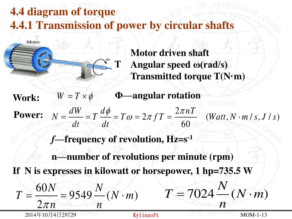
The following reading, from an Air Force stress manual, provides the key formula for relating horsepower to torque, which is very common in aerospace and automotive applications.
Transmission Shafting Analysis
This section from the 'Transmission Shafting Analysis' manual provides the direct, formula-based relationship between horsepower, rotational speed, and torque.
Please read Section 10.3 'Loadings on Circular Transmission Shafting'. Focus on Equation (10-2), which gives the torque T (in in-lbs) from horsepower (hp) and speed n (in rpm). This is a vital formula for practical design problems.
The key formulas for power transmission are:
- SI Units: where is in Watts, is in rpm, and is in N·m.
- Imperial Units: or
5. Shafts with Multiple Torques
Often, a single shaft is subjected to torques at multiple points, such as in a gearbox or an engine accessory drive. To find the stress in any given section, you must first determine the internal torque in that section. The process is very similar to how you would find internal axial forces. You make an imaginary "cut" and use the equations of equilibrium. Plotting the internal torque along the shaft's length creates a torque diagram.
The following video provides an excellent worked example of this entire process.
Mechanics of Materials: Lesson 23 - Shear Stress Due to Torsion, Polar Moment of Inertia
This video by Jeff Hanson, 'Mechanics of Materials: Lesson 23', is a perfect practical example. He first plots the internal torque for a shaft with multiple applied loads and then calculates the shear stress in each section.
Watch from 5:33 to the end (16:47). First, observe how he calculates and plots the internal torque diagram using the 'cover-up' method. Then, see how he applies the torsion formula to find the shear stress in each distinct section of the shaft. This demonstrates the full analysis process.
Conclusion
In this lesson, we moved from bending analysis to torsional analysis, a critical skill for designing rotating machinery. You learned how to quantify a shaft's resistance to twisting and how to calculate the resulting stresses and deformations.
Key Takeaways:
- Torsion is the twisting of a member due to an applied torque ().
- The polar moment of inertia () is the geometric property that measures a circular shaft's resistance to torsion.
- Torsional shear stress () is calculated with the torsion formula: . It is zero at the center and maximum at the outer surface.
- The angle of twist () is the rotational deformation of the shaft, calculated by .
- Power transmission relates power, torque, and speed, allowing you to determine the torque on a shaft from engine specifications.
- For shafts with multiple loads, you must first determine the internal torque in each section before calculating stress.
Next Lesson Preview:
The method you just saw for creating an internal torque diagram—making cuts and applying equilibrium—is a powerful tool. In the next lesson, we will apply the exact same logic to beams under bending loads. We will learn to construct shear force and bending moment diagrams, which are essential for finding the maximum bending stress in any beam.
Can't find a good explanation? Sign up and we'll make it for you
Sign up