
Hello! Welcome to the final lesson in our module on the planar kinetics of rigid bodies.
In the last lesson, we used the principle of work and energy to relate forces, displacement, and changes in speed. This scalar method is incredibly effective when you're analyzing motion over a specific distance.
Today, we'll explore the principle of impulse and momentum. This is a powerful vector method that connects forces, the time over which they act, and the resulting change in velocity. It's the go-to tool for analyzing situations involving short-duration forces, impacts, and collisions—scenarios common in aerospace, such as landing gear touchdowns or payload deployment mechanisms.
Your learning outcome for this lesson is to apply the principles of linear and angular impulse-momentum to rigid bodies.
1. Contrasting Work-Energy with Impulse-Momentum
Before we dive in, let's clarify when you would choose one method over the other:
| Feature | Work-Energy Principle | Impulse-Momentum Principle |
|---|---|---|
| Core Idea | Force applied over a distance | Force applied over a time interval |
| Equation Type | Scalar () | Vector () |
| Key Variables | Force, displacement, velocity | Force, time, velocity |
| Best For... | Problems involving springs, gravity, and finding changes in speed after moving a certain distance. | Problems involving impacts, collisions, and finding velocity changes after a force acts for a specific duration. |
2. The Principle of Impulse and Momentum
The core idea is that the initial momentum of a body, plus the impulse applied to it, equals its final momentum. For rigid bodies, we have two separate but related principles: one for linear motion and one for angular motion.
This diagram provides a great visual summary of the principle. It shows that by integrating the equations of motion ( and ) with respect to time, we arrive at the impulse-momentum equations.
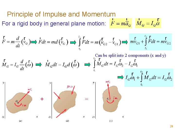
The diagram illustrates a crucial problem-solving tool: the impulse-momentum diagram. We draw the body's momentum at time , add the impulses applied between and , and set it equal to the momentum at time .
Let's break down the components.
2.1 Linear Impulse and Momentum
- Linear Momentum (): This is the momentum of the body's center of mass, . It's a vector quantity defined as:
- Linear Impulse (): This is the effect of a force applied over a time interval from to . It's the integral of the force with respect to time:
If the force is constant, this simplifies to .
The Principle of Linear Impulse-Momentum combines these:
Since this is a vector equation, we can break it into x and y components for 2D problems.
2.2 Angular Impulse and Momentum
- Angular Momentum (): This is the "moment" of the linear momentum and also accounts for the body's rotation. For planar motion, its magnitude is most often calculated about the center of mass :
- Angular Impulse (): This is the effect of a moment applied over a time interval.
If the moment is constant, this simplifies to . An angular impulse can be created by a pure couple moment or by an off-center force ().
The Principle of Angular Impulse-Momentum (about the center of mass G) is:
This clear and concise web page summarizes these fundamental equations.
The Impulse Momentum Theorem for a Rigid Body
Refer to this section from Eng.LibreTexts to see the primary impulse-momentum equations for rigid bodies laid out clearly.
Read the first part of this page, focusing on the two main vector equations for linear and angular impulse-momentum. Note the key points about using vector components and being consistent with the reference point for angular momentum.
3. A Complete Overview and Worked Examples
The best way to see how these principles work together is through guided examples. The following video first reviews the definitions we just discussed and then solves three different problems, showing how to apply the equations in practice.
Rigid Bodies Impulse and Momentum Dynamics (Learn to solve any question)
This video from Question Solutions provides a complete tutorial on solving impulse-momentum problems for rigid bodies. It covers the theory and then applies it to practical examples.
Please watch the full video (around 13.5 minutes). 0:00 - 3:39: This part reviews the definitions of linear and angular momentum/impulse for different types of motion and presents the three governing equations. This will reinforce what we just covered. 4:03 - 8:12: The first example (gear and rack) is a great case of general plane motion where you need to use both linear and angular impulse-momentum equations to find the solution. 8:12 - 10:25: The second example (pulleys and a block) demonstrates how to handle connected bodies in fixed-axis rotation. 10:25 - 13:47: The final example involves a variable torque that requires integration, showing how to handle non-constant impulses.
4. Conservation of Momentum
A very important special case of the impulse-momentum principle occurs when there is no external impulse acting on a system over the time interval.
- Conservation of Linear Momentum: If , then . The linear momentum is conserved.
- Conservation of Angular Momentum: If , then . The angular momentum is conserved.
A classic example is a figure skater pulling their arms in. By reducing their mass moment of inertia (), their angular velocity () must increase to keep the angular momentum () constant. This principle is fundamental in controlling the attitude (orientation) of satellites and spacecraft using reaction wheels or thrusters.
The following text provides a good explanation of this concept.
Conservation of Angular Momentum
This section of the LibreTexts page explains the conditions for conservation of momentum and gives practical examples.
Read the section titled 'Conservation of Angular Momentum'. Pay attention to the two main instances where it's applied: spinning bodies changing shape, and rigid body collisions.
5. Test Your Understanding
Let's apply these principles to an aerospace problem.
A 750 kg helicopter body (excluding the main rotor) has a mass moment of inertia about its center of mass . The main rotor suddenly speeds up, causing the helicopter body to start rotating counter-clockwise at .
To counteract this, the pilot uses the tail rotor, which provides a horizontal thrust . The tail rotor is located 6 m from the helicopter's center of mass.
If the tail rotor provides a constant thrust of N, how long must this thrust be applied to stop the helicopter body's rotation (i.e., to make )?
Diagram: A top-down view of a helicopter. The body has an initial angular velocity ω1. A thrust T from the tail rotor is applied at a distance d from the center of mass G.
Problem-Solving Steps:
- Identify which principle to use: linear or angular impulse-momentum?
- Write down the chosen equation: Initial Momentum + Impulse = Final Momentum.
- Calculate the initial angular momentum, .
- Determine the angular impulse caused by the tail rotor thrust. Remember that an off-center force creates a moment. Is the impulse positive or negative relative to the initial rotation?
- What is the final angular momentum?
- Substitute the values into the equation and solve for the unknown time, .
Test your understanding!
Let's walk through the solution.
-
Principle: Since we're dealing with rotation and a force applied over time to stop it, the principle of angular impulse-momentum is the correct choice. We will consider counter-clockwise (CCW) as the positive direction.
-
Equation:
-
Initial Angular Momentum: The body is rotating CCW, which we defined as positive.
-
Angular Impulse: The tail rotor thrust creates a moment about . The force is 450 N and the moment arm is 6 m. This moment will cause a clockwise (negative) rotation to counteract the initial CCW spin.
Since the thrust is constant, the angular impulse is: -
Final Angular Momentum: The goal is to stop the rotation, so .
-
Solve for :
So, the tail rotor must provide thrust for about 0.24 seconds to stop the unwanted rotation. This shows just how responsive these systems need to be!
Conclusion
You have now completed the core topics of planar rigid body kinetics! You have three powerful methods at your disposal:
- Equations of Motion (): For finding forces and accelerations at a single instant.
- Work and Energy: For relating forces, distance, and speed (scalar).
- Impulse and Momentum: For relating forces, time, and velocity (vector), especially useful for impacts.
Key Takeaways from this Lesson:
- The principle of impulse-momentum relates the initial and final states of motion of a body when forces and moments are applied over a time interval.
- The principle is expressed in two vector equations: one for linear motion () and one for angular motion ().
- When the net external impulse (linear or angular) on a system is zero, the corresponding momentum is conserved. This is a crucial concept for analyzing collisions and control systems.
Next Lesson Preview:
We will now move on to a new topic: Mechanical Vibrations. In the next module, you will learn how to derive the equation of motion for a simple oscillating system (a spring-mass system). This is the foundation for understanding how structures and machines, from aircraft wings to engine components, respond to dynamic loads, and it's a critical area of study in mechanical and aerospace engineering.
Can't find a good explanation? Sign up and we'll make it for you
Sign up