
Hello! Welcome to the first lesson in our new module, "Instrumentation for Motion and Behavior Analysis."
In our last lesson, we designed a multimodal system to assess stress by combining signals like EDA, HRV, and EEG. We concluded that physiological data is powerful but lacks context. For example, a high heart rate could signify anxiety or a brisk walk. To build a truly intelligent system for your startup, Neuraease, we need to understand a person's physical activity.
This lesson introduces the core components of motion tracking. We will focus on the learning outcome: Explain the operating principles of accelerometers and gyroscopes for motion tracking. We'll dive into the microscopic mechanical systems that allow our devices to sense movement, acceleration, and rotation.
1. From Physiology to Physics: The Need for Motion Context
Before we begin, let's solidify the "why." For a wearable device like the one you're developing, motion data is critical for three main reasons:
- Contextualization: It helps you differentiate between physiological responses caused by emotional stress and those caused by physical exertion.
- Artifact Rejection: It allows you to identify and remove noise in other sensor signals (like PPG or EEG) that is caused by movement.
- Behavioral Analysis: It enables the detection of specific motor patterns, such as restlessness or repetitive movements, which can be important behavioral indicators.
The sensors that provide this data are accelerometers and gyroscopes, typically packaged together in a single chip called an Inertial Measurement Unit (IMU). Let's look at how each one works.
2. The Accelerometer: Measuring Linear Motion
An accelerometer measures linear acceleration—the rate of change of velocity along a straight line. Its operation is rooted in Newton's second law () and realized using Micro-Electro-Mechanical Systems (MEMS).
Conceptually, a MEMS accelerometer is like a tiny "ball on a spring" or, more accurately, a proof mass suspended by flexible silicon springs.
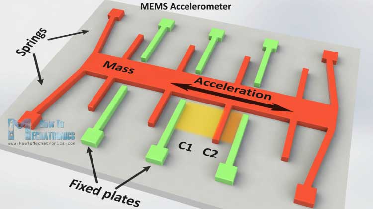
When the device accelerates, the frame moves but inertia causes the proof mass to lag behind. This changes the distance between the proof mass and a set of fixed electrodes. This change in distance is measured as a change in capacitance.
To see this principle in action, let's watch a video that provides an excellent 3D animation of the process.
How does an Accelerometer work? | 3D Animation
This video from CircuitBread clearly explains the capacitive sensing mechanism inside a MEMS accelerometer. It will help you visualize the proof mass, sense fingers, and the differential capacitor structure.
Please watch from 0:53 to 3:29. Focus on understanding: The components: proof mass, sense fingers, and fixed electrodes. How acceleration causes the distance between the 'plates' of the capacitor to change. The concept of a 'differential capacitor' where the capacitance increases on one side and decreases on the other.
The key takeaway is that the sensor's electronics measure this change in differential capacitance and convert it into a voltage proportional to the acceleration.
Measuring in 3D and the Influence of Gravity
To measure motion in three dimensions (X, Y, Z), manufacturers simply integrate three of these sensor structures onto a single chip, oriented at 90-degree angles to each other.
An important and often confusing aspect of accelerometers is that they also measure the constant acceleration due to gravity. When an accelerometer is stationary, it doesn't read zero. Instead, it measures the 1 g () pull of gravity. The sensor cannot distinguish between acceleration from motion and the pseudo-acceleration from gravity.
For a deeper look at this, the following reading clarifies the concept.
Learn about MEMS accelerometers, gyroscopes, and ...
This article from VectorNav provides a concise explanation of the accelerometer's operating principle, including the important effect of gravity.
Please read the section 'MEMS Accelerometers'. Pay close attention to the paragraphs explaining why an accelerometer at rest measures -1 g along its vertical axis and why it measures zero during free fall.
This property is both a challenge and a feature. It's a challenge because we have to separate gravity from motion to calculate pure movement. It's a feature because the gravity vector tells us the device's tilt or orientation relative to the ground.
Test your understanding!
Imagine you are holding your smartphone flat, with the screen facing up. The z-axis of the phone's accelerometer points out of the screen, the y-axis points toward the top edge, and the x-axis points toward the right edge.
- What approximate values (in g's) would you expect the accelerometer to report for the x, y, and z axes?
- What would the accelerometer report for all three axes if you dropped the phone (i.e., it's in freefall)?
Show answer
- When the phone is flat, the force of gravity is acting downwards, opposite to the z-axis. Therefore, the accelerometer would report approximately:
- x-axis: 0 g
- y-axis: 0 g
- z-axis: +1 g (or -1 g, depending on the sensor's coordinate system convention, but it will be a non-zero value on the vertical axis).
- During freefall, both the accelerometer's frame and its internal proof mass are accelerating towards the Earth at the same rate (1 g). There is no relative displacement of the proof mass. Therefore, the accelerometer would report 0 g on all three axes. This is why this state is sometimes called "zero-g."
3. The Gyroscope: Measuring Angular Motion
While an accelerometer measures linear motion, a gyroscope measures angular velocity—how fast the device is rotating around an axis (e.g., in degrees per second).
MEMS gyroscopes operate on a more complex principle: the Coriolis effect. The Coriolis effect is an inertial force that acts on a mass moving in a rotating frame of reference.
Inside a MEMS gyroscope, a proof mass is kept in a state of constant oscillation (vibrating back and forth). When you rotate the device, the Coriolis effect exerts a force on this vibrating mass, pushing it perpendicular to its direction of vibration. This secondary displacement is detected, once again, by a change in capacitance. The magnitude of this displacement is directly proportional to the rate of rotation.
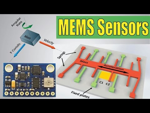
The following video provides an excellent animated explanation of this principle.
How Gyroscope Sensor Works ? | 3D Animated 🔥
This animation from Blue Butterfly will help you visualize the Coriolis effect inside a MEMS gyroscope. It clearly shows how an applied rotation creates a measurable perpendicular force.
Please watch from 2:16 to 4:26. Don't worry about memorizing the M1-M4 mass names. Focus on the core concept: A mass is kept oscillating at a constant frequency. When an external rotation is applied, the Coriolis effect causes the mass to move perpendicularly. This perpendicular movement causes a change in capacitance, which is measured to determine the angular rate. Note how different axes of rotation (roll, pitch, yaw) affect the masses differently.
The Tuning Fork Design
A common problem is that a simple gyroscope could be "fooled" by linear acceleration (like a bump or vibration). To solve this, engineers use a tuning fork design, where two masses vibrate in opposite directions.
When the device is rotated, the Coriolis forces on the two masses also act in opposite directions, producing a strong differential signal. However, if the device is subjected to a linear acceleration, both masses move in the same direction, producing no net change in capacitance. This clever design makes the gyroscope sensitive to rotation but largely immune to linear shocks. You can find more details on this in the "MEMS Gyroscopes" section of the VectorNav article (LINK) we looked at earlier.
4. Complementary Sensors for a Complete Picture
Accelerometers and gyroscopes each have unique strengths and weaknesses:
- Accelerometers:
- Strength: Can measure static orientation (tilt) relative to gravity. They don't drift over long periods when measuring tilt.
- Weakness: Noisy for tracking dynamic motion. Integrating acceleration to get velocity and position leads to rapidly accumulating errors. They can't distinguish gravity from linear motion.
- Gyroscopes:
- Strength: Excellent at measuring rotation and tracking orientation changes over short periods. Unaffected by gravity.
- Weakness: Suffer from drift. Small errors in the angular velocity measurement accumulate over time, causing the calculated orientation to slowly drift away from the true orientation.
Because of this, they are almost always used together. The accelerometer provides a stable, long-term reference (gravity), while the gyroscope provides clean, responsive short-term rotation data.
MEMS Accelerometers and Gyroscopes
To tie this all together, please read the conclusion of this article which perfectly summarizes the complementary nature of these two sensors.
Please read the 'Conclusion' section. It highlights how the strengths of one sensor compensate for the weaknesses of the other, setting the stage for why we need to combine their data.
Conclusion
In this lesson, we have demystified the inner workings of the sensors that form the foundation of motion tracking in nearly every modern electronic device.
Key Takeaways:
- Accelerometers measure linear acceleration using a proof mass and capacitive sensing. They are sensitive to both motion and gravity, which allows them to measure tilt.
- Gyroscopes measure angular velocity by detecting the Coriolis effect on a constantly vibrating mass. They are designed to be sensitive to rotation but immune to linear acceleration.
- These sensors are complementary: the accelerometer provides a stable gravity reference, while the gyroscope provides clean rotation data. Neither is sufficient on its own for robust orientation tracking.
Preview of the Next Lesson:
Now that we understand how these sensors work and why they are used together, our next step is to answer the question: "How do we actually combine their data?" In the next lesson, we will explore sensor fusion techniques, such as the use of Kalman filters and complementary filters, to merge accelerometer and gyroscope data into a single, stable, and accurate estimate of 3D orientation.
Can't find a good explanation? Sign up and we'll make it for you
Sign up