
Welcome back. In the previous lesson, you learned to read board-level Device Tree changes as a hardware contract: inherited SoC facts describe the silicon, while the board DTS enables only the interfaces that are actually routed and populated. This time you will turn that understanding into an engineering workflow: produce a DTB, inspect the effective compiled tree, validate it at multiple levels, and correct an address-cell error rather than merely silencing a warning.
The immediate target is a small local lab, not an AM62x board deployment. That is intentional: it lets you learn the toolchain and failure signatures safely before modifying a vendor kernel tree. The same validation loop will later protect your AM62x CAN-FD, Ethernet, GPIO, and sensor changes.
What a successful DTB workflow proves
A .dts file is source code for a hardware description; a .dtb is its flattened binary representation. During a normal kernel build, the DTS is first preprocessed—expanding includes and macros—then compiled by the Device Tree Compiler, dtc.
There are three distinct questions to answer:
| Question | Tooling | What it catches |
|---|---|---|
| Is the source structurally well formed? | dtc | Syntax errors, unresolved labels, malformed reg length, duplicate names, selected generic consistency checks |
| Does the description obey the hardware binding? | Kernel dtbs_check | Missing required properties, invalid compatible strings, invalid phandle specifiers, illegal values and node layouts |
| Did Linux receive and use the intended tree? | Boot logs, /sys/firmware/devicetree/base, driver evidence | Wrong deployed DTB, U-Boot fixups, probe failures, wiring or pinmux problems |
The distinction matters. dtc understands tree structure but does not understand every hardware binding. It can compile a tree containing an invented compatible string or an electrically impossible pin selection. Schema validation provides the next level of assurance, and boot-time evidence provides the final one.
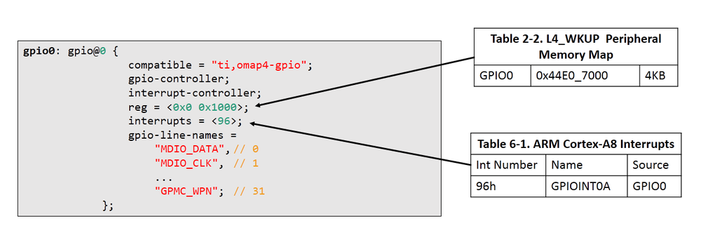
The GPIO controller mapping image illustrates this separation between description and hardware reality. Its reg property corresponds to a peripheral memory-map entry; its interrupts property corresponds to an interrupt-controller table entry. The values shown are specific to the illustrated platform, not AM62x values to reuse.
Read the relevant parts of DTC manual to establish the supported source and binary formats, the essential command-line model, and the role of fdtdump.
In “3) Command Line,” read the input, output, and checking overview. Focus on the distinction between dts, dtb, and the filesystem representation (fs), then note that the compiler performs sanity checks in addition to format conversion. In “IV - Utility Tools,” read the short fdtdump subsection to see where it fits: use it for a readable dump when diagnosing a binary artifact, but prefer dtc -I dtb -O dts when you need editable decompiled source.
Compile and decompile: inspect the artifact, not only the source
First verify that dtc exists on the Ubuntu host:
dtc --version
If it is not installed, install the Ubuntu package device-tree-compiler using the APT workflow established earlier, then re-run the version command.
For a standalone DTS with no kernel-specific includes, compilation is direct:
dtc -I dts -O dtb -o lab.dtb lab.dts
The options mean:
-I dts: interpret the input as Device Tree Source.-O dtb: produce a binary Device Tree Blob.-o lab.dtb: write the result to the named artifact.
Decompile the resulting binary immediately:
dtc -I dtb -O dts -o lab.decompiled.dts lab.dtb
This is not a textual round trip. The decompiled output normally loses comments, original include-file boundaries, formatting choices, and much of the source-level intent. It shows what the consumer receives after the tree has been flattened: merged nodes, final overridden property values, numeric phandles where appropriate, and binary-encoded values rendered as DTS cells.
For an additional, read-only binary inspection:
fdtdump lab.dtb | less
Use fdtdump when a DTB is the only artifact available—for example, one extracted from a boot partition—and you need a quick readable view. Use decompilation when you want to compare a compiled artifact against expected final properties.
For a real AM62x kernel tree, do not normally invoke dtc directly on a board DTS. AM62x DTS files rely on kernel include paths, C preprocessor macros, and generated headers. Let the kernel build system create the final command line.
3.2.1. Users Guide — Processor SDK AM62x Documentation
Read Texas Instruments’ AM62x SDK guidance to locate board DTS files and connect a board source file to its generated DTB.
In Section “3.2.1.5.2 Compiling the Device Tree Binaries,” read the AM62x DTB build guidance. Pay particular attention to the AM62x SK mapping from k3-am625-sk.dts to its DTB and to the stated arch/arm64/boot/dts/ti source and output location. On a derivative board, first confirm the actual board DTS and vendor-kernel revision; never assume the reference-board filename is the DTB loaded by your boot flow.
A typical targeted kernel build follows this pattern:
make ARCH=arm64 CROSS_COMPILE=aarch64-linux-gnu- \
    arch/arm64/boot/dts/ti/<your-board>.dtb
Replace <your-board> with the DTS basename selected by your kernel configuration and board. If your vendor SDK supplies a toolchain environment, use its documented CROSS_COMPILE prefix rather than assuming aarch64-linux-gnu-.
The generated file usually appears under:
arch/arm64/boot/dts/ti/
For a broad rebuild during active board work:
make ARCH=arm64 CROSS_COMPILE=aarch64-linux-gnu- dtbs
Targeted builds are usually the better iteration loop: they reduce build time and make it clearer which artifact you intend to deploy.
The address-cell rule: the parent defines a child’s reg encoding
The most common conceptual error is to interpret reg locally. Its encoding is defined by the parent node.
Suppose a parent I2C controller declares:
#address-cells = <1>;
#size-cells = <0>;
Every direct child’s reg must therefore contain:
- one cell for its I2C address;
- zero cells for a size.
A sensor at I2C address 0x48 is correctly described as:
sensor@48 {
        compatible = "vendor,example-sensor";
        reg = <0x48>;
};
The node name’s unit address, @48, agrees with the first address encoded in reg.
The controller itself follows a different rule. If it is a child of an SoC bus declaring one address cell and one size cell, the controller’s own reg needs two cells:
i2c@2000 {
        reg = <0x2000 0x100>;

        #address-cells = <1>;
        #size-cells = <0>;

        /* These cell declarations affect children, not i2c@2000 itself. */
};
This “look upward first” rule prevents a large class of errors:
- Find the node containing the
regproperty. - Move to its immediate parent.
- Read the parent’s
#address-cellsand#size-cells. - Count the cells required for each address-size tuple.
- Check that the unit address agrees with the first encoded address when applicable.
Device Tree 101 10:00 AM UTC+1 session
Watch these two excerpts from Device Tree 101 by Bootlin. They distinguish generic compiler checks from binding-based semantic validation, then give a precise explanation of address and size cells.
Watch binding validation first. Focus on why a DTS that passes dtc can still violate the binding, and on the purpose of the kernel dtbs_check target. Then watch cell encoding. Track the key rule: #address-cells and #size-cells belong to a parent and define the reg layout of that parent’s direct children.
Lab: create, diagnose, and fix an address-cell error
Create a working directory that is separate from a vendor kernel checkout:
mkdir -p ~/dtb-lab
cd ~/dtb-lab
Create address-cells-broken.dts with the following deliberately faulty source:
/dts-v1/;

/ {
        compatible = "grasp,dtb-validation-lab";
        #address-cells = <2>;
        #size-cells = <2>;

        soc {
                compatible = "simple-bus";
                #address-cells = <1>;
                #size-cells = <1>;
                ranges = <0x0 0x0 0x10000000 0x00100000>;

                i2c@2000 {
                        compatible = "vendor,example-i2c";
                        reg = <0x2000 0x100>;

                        #address-cells = <1>;
                        #size-cells = <0>;

                        sensor@48 {
                                compatible = "vendor,example-sensor";
                                reg = <0x00 0x48>;
                        };
                };
        };
};
Compile it while retaining the full diagnostic output:
dtc -I dts -O dtb -o address-cells-broken.dtb \
    address-cells-broken.dts 2>&1 | tee address-cells-broken.log
The precise wording depends on the installed dtc version, but expect a warning in the reg_format family. It should indicate that the sensor@48 node’s reg length does not agree with its parent’s address- and size-cell declarations.
Do not be misled if dtc still creates a .dtb. A generated binary is not evidence that the design is valid. Treat any warning as a defect requiring an explanation or correction.
Trace the error mechanically:
| Node | Parent’s cell rule | Required reg representation | Actual representation |
|---|---|---|---|
i2c@2000 | soc has one address cell and one size cell | <base length> | <0x2000 0x100> — correct |
sensor@48 | i2c@2000 has one address cell and zero size cells | <i2c-address> | <0x00 0x48> — incorrect: two cells |
The incorrect sensor node is not a 64-bit address. It is an I2C child whose reg must encode one bus address. Correct the property in a new file, address-cells-fixed.dts:
/dts-v1/;

/ {
        compatible = "grasp,dtb-validation-lab";
        #address-cells = <2>;
        #size-cells = <2>;

        soc {
                compatible = "simple-bus";
                #address-cells = <1>;
                #size-cells = <1>;
                ranges = <0x0 0x0 0x10000000 0x00100000>;

                i2c@2000 {
                        compatible = "vendor,example-i2c";
                        reg = <0x2000 0x100>;

                        #address-cells = <1>;
                        #size-cells = <0>;

                        sensor@48 {
                                compatible = "vendor,example-sensor";
                                reg = <0x48>;
                        };
                };
        };
};
Now compile and decompile the corrected artifact:
dtc -I dts -O dtb -o address-cells-fixed.dtb \
    address-cells-fixed.dts

dtc -I dtb -O dts -o address-cells-fixed.decompiled.dts \
    address-cells-fixed.dtb
Inspect the final node:
grep -A4 -B1 'sensor@48' address-cells-fixed.decompiled.dts
The essential evidence is that:
- compilation completes with no diagnostic;
sensor@48containsreg = <0x48>;;- the parent I2C node still declares
#address-cells = <1>;and#size-cells = <0>;; - the unit address and encoded bus address agree.
Record the original diagnostic, corrected DTS, commands, tool version, and resulting DTB hash in the private project repository. This is the kind of compact bring-up evidence that later supports a credible design review without exposing proprietary board details.
Schema validation in a real kernel tree
The lab above validates a structural rule, but its fictional compatible strings have no kernel binding. In actual AM62x work, validate against the real binding associated with the node’s compatible.
First, find the relevant binding from the kernel source:
grep -RIn 'your,compatible-string' Documentation/devicetree/bindings/
Then run a focused schema check from the configured kernel tree:
make ARCH=arm64 CROSS_COMPILE=aarch64-linux-gnu- \
    DT_SCHEMA_FILES="Documentation/devicetree/bindings/<binding-path>.yaml" \
    dtbs_check
Replace <binding-path> with the real path discovered by the search. A focused check reduces noise while you iterate. Before integration or release, also run the full architecture-relevant check:
make ARCH=arm64 CROSS_COMPILE=aarch64-linux-gnu- dtbs_check
Typical schema findings include:
- a required supply, clock, interrupt, reset, or pin-control property is absent;
- a
compatiblevalue is not permitted by the binding; - an array has the wrong number of cells;
- a GPIO, clock, or interrupt phandle carries the wrong number of provider-defined specifier cells;
- a child node is placed under the wrong bus or has an invalid
regform.
Schema validation answers “does this description follow the documented software contract?” It does not prove that a sensor is physically populated at that address, that a CAN transceiver is powered, or that a pinmux setting matches the schematic. Those remain board-level verification tasks.
A compact phandle-error triage method
Although this lesson’s correction used address cells, phandle failures follow the same evidence-driven pattern.
If compilation reports an unresolved label such as a reference to &gateway_sensor_pins that does not exist, work through these checks:
-
Find the consumer.
Identify the property containing the reference, such aspinctrl-0,clocks,reset-gpios, orinterrupt-parent. -
Find the provider.
Search the complete include chain for the label definition. Remember that a label may exist in an SoC.dtsi, a common board.dtsi, or the top-level board DTS. -
Check that the provider is appropriate.
A label resolving successfully does not prove it identifies the correct GPIO controller, pinctrl state, or clock controller. -
Check provider cell counts.
For example, a clock reference must supply exactly the number of cells defined by that provider’s#clock-cells; a GPIO specifier follows#gpio-cells. -
Inspect the final DTB.
Compile and decompile it. This exposes the merged result after board-level overrides and includes have been applied.
The following pattern is valid only when the referenced pin-state label is actually defined in the resulting tree:
&main_i2c1 {
        pinctrl-names = "default";
        pinctrl-0 = <&gateway_i2c1_pins_default>;
        status = "okay";
};
A common failure is to copy this consumer fragment but omit the pin-controller state definition, rename its label, or define it in a DTS file that the final board DTS does not include.
Validate the DTB Linux actually received
Once you begin deploying DTBs to the AM62x board, compare the intended build artifact with the tree that Linux receives. U-Boot may apply fixups, select a different file than expected, or populate /chosen at boot.
On the target, decompile the live Device Tree filesystem:
dtc -I fs -O dts -o running-tree.dts /sys/firmware/devicetree/base
Then inspect the relevant node:
grep -A12 -B2 'main_i2c1' running-tree.dts
The fs input format reads the directory-and-property-file representation exported by Linux. It is particularly valuable when the source DTS looks correct but the booted system behaves as though the node were disabled or incorrectly configured.
For a board peripheral, close the validation loop with runtime evidence:
- confirm the expected compatible device was probed in the kernel log;
- inspect the corresponding subsystem entry in
/sys; - verify the expected driver has bound;
- for an I2C component, confirm its bus address and driver binding;
- for GPIO or CAN, verify the associated controller and pin state are active without conflicting with another board function.
Key takeaways
A dependable Device Tree change is verified in layers.
- Compile standalone DTS files with
dtc -I dts -O dtb; decompile binaries withdtc -I dtb -O dts. - For AM62x kernel DTS files, use the kernel build system so preprocessing, include paths, macros, and the configured target architecture are handled correctly.
- A successful
.dtbfile alone is insufficient:dtcdiagnostics, schema validation, and runtime evidence answer different questions. - A child node’s
regencoding is defined by its parent’s#address-cellsand#size-cells. - The parent’s cell declarations affect its children, not its own
reg. dtbs_checkvalidates a DTS against YAML bindings and catches semantic errors thatdtccannot understand./sys/firmware/devicetree/basereveals the Device Tree Linux actually received after firmware and U-Boot processing.
Next, you will connect this compiled DTB to the boot contract itself: the ARM64 U-Boot-to-kernel register handoff, early head.S execution, MMU activation, and entry into start_kernel().
Can't find a good explanation? Sign up and we'll make it for you
Sign up