
Good to see you again. In the previous lesson, you built a U-Boot policy that loads a kernel, DTB, and initramfs into non-overlapping DRAM ranges. The DTB in that handoff is not a passive file: it is the hardware contract Linux uses to decide which drivers to probe, which register blocks to map, which interrupts to request, which clocks to enable, and how physical pads are routed.
This lesson develops the ability to read that contract and make disciplined board-level changes. You will work with the properties most often encountered during AM62x gateway bring-up: compatible, reg, interrupts, clocks, phandles, /aliases, /chosen, and pinctrl.
Device Tree: a description of hardware that cannot introduce itself
Many embedded devices are not discoverable. Linux cannot scan an AM62x memory map and reliably infer that a particular UART is routed to the debug connector, that a CAN transceiver is fitted, or that an I2C temperature sensor is present at a particular bus address. It also cannot infer the electrical configuration required to route an SoC peripheral signal to a package pin.
The Device Tree provides these facts. Its source form is usually a Device Tree Source file (.dts) plus one or more Device Tree Source Include files (.dtsi). The compiled binary passed by U-Boot to Linux is the Device Tree Blob (.dtb).
A useful mental model is:
- A node represents a hardware block, bus, or logical platform object.
- A property gives a fact about that node.
- The node hierarchy usually reflects containment or connection: an I2C sensor is a child of its I2C controller; an SoC peripheral normally appears below an SoC bus node.
- A label gives a source-level name to a node.
- A phandle reference connects one node to another without duplicating its details.
For board work, avoid treating the DTS as a configuration file in the ordinary application sense. It should describe physical hardware topology: which hardware exists, where it is, and how it connects. Linux policy belongs elsewhere unless a binding explicitly defines it.
Device Tree: hardware description for everybody !
Watch Bootlin's “Device Tree: hardware description for everybody!” for the motivation, source structure, and board-versus-SoC layering model. It establishes why a gateway board needs a DT description even when the kernel driver already exists.
Watch why DT exists to distinguish discoverable buses such as PCIe and USB from fixed hardware such as MMIO, I2C, and SPI devices. Then watch nodes and properties for the basic tree vocabulary. Finish with DTS layering, focusing on why SoC details belong in shared .dtsi files and board-specific changes belong in a board .dts.
Reading a node from the outside inward
Consider this intentionally generic peripheral node:
peripheral@2800000 {
        compatible = "vendor,soc-peripheral", "vendor,peripheral";
        reg = <0x00 0x02800000 0x00 0x1000>;
        interrupts = <GIC_SPI 123 IRQ_TYPE_LEVEL_HIGH>;
        clocks = <&clock_controller 42 0>;
        clock-names = "fck";
        status = "okay";
};
The names and numeric values are illustrative only. Do not copy them into an AM62x tree. The relevant binding and the SoC include file determine the actual strings, addresses, interrupt specifiers, and clock specifiers.
Read the node as a sequence of questions:
-
What programming model is this?
compatibleidentifies the hardware interface exposed to software. -
Where are its resources?
reglocates a register block, bus address, chip select, or another resource depending on the parent bus. -
How does it notify the CPU?
interruptsdescribes the interrupt source in the interrupt controller’s format. -
What must supply its functional clock?
clocksreferences a clock provider and identifies the required clock within that provider. -
Is the hardware available on this particular board?
status = "okay"allows the OS to use it. A SoC.dtsicommonly marks optional peripherals as"disabled", and a board DTS enables only the ones physically connected.
The syntax is C-like, but the semantics come from the binding for the device. A syntactically valid node can still be electrically impossible, semantically invalid, or mapped to the wrong driver.
The core resource properties
The table below gives a practical interpretation of the properties you will inspect most frequently.
| Property | Question it answers | Typical meaning | Common failure when wrong |
|---|---|---|---|
compatible | Which programming model and driver apply? | Ordered list from most specific to more general compatible models | No driver probes, or a driver uses incorrect variant behavior |
reg | Where is the resource on its parent bus? | MMIO base and length; I2C address; SPI chip-select index | Driver accesses the wrong registers or cannot communicate with a child device |
interrupts | Which interrupt source does this device generate? | Binding-defined interrupt specifier | Driver probes but interrupts never arrive, or an unrelated IRQ fires |
interrupt-parent | Which controller interprets interrupts? | Phandle to an interrupt controller; may be inherited | Interrupt specifier is decoded in the wrong domain |
clocks | Which clock resource must be acquired? | Phandle plus provider-defined specifier cells | Peripheral remains gated, hangs, or times out |
pinctrl-0 | Which pin state applies to the device’s default operation? | Phandle list to one or more pin-control state nodes | Peripheral exists but signals do not reach its physical pins |
pinctrl-names | What is each pin-control state called? | Often "default", sometimes "sleep" | Driver cannot select the intended state |
status | Should this node be operational on this board? | Commonly "okay" or "disabled" | Valid hardware is not probed, or unconnected hardware is wrongly enabled |
compatible: driver selection, not marketing text
compatible is an ordered list of strings. It runs from the most precise model to a more general fallback:
compatible = "vendor,soc-revision-peripheral", "vendor,peripheral";
Linux tries to match the most specific compatible model that the driver supports. The generic fallback allows a common driver to support a family of related IP blocks while applying variant-specific behavior when necessary.
Do not invent a compatible string because the driver name looks plausible. Find it in one of these places:
- the existing SoC or board DTS/DTSI;
- the YAML binding in the kernel source under
Documentation/devicetree/bindings/; - the driver’s
of_match_tablewhere appropriate; - a vendor-supported board DTS for the same SoC family and peripheral.
For an external board component, the compatible usually describes the actual component, such as a particular CAN transceiver controller, GPIO expander, sensor, or Ethernet PHY. For a built-in AM62x peripheral, it usually identifies the SoC IP block.
reg: the parent bus defines its meaning
A critical rule is that reg does not always mean “physical address plus byte size.”
For a memory-mapped SoC peripheral, reg normally contains an address and a length. Its representation is governed by the parent node’s #address-cells and #size-cells.
For example, if the parent defines:
#address-cells = <1>;
#size-cells = <1>;
then this child has one address cell and one size cell:
serial@4600 {
        reg = <0x4600 0x100>;
};
The unit address in serial@4600 must match the first address represented by reg.
By contrast, an I2C controller may declare:
#address-cells = <1>;
#size-cells = <0>;
An I2C sensor below it can then use its bus address alone:
sensor@48 {
        reg = <0x48>;
};
Here 0x48 is the device’s I2C slave address, not a CPU physical address. An SPI child’s reg commonly identifies a chip-select. Always establish the parent bus type and its cell rules before interpreting or modifying reg.
Devicetree Specification unknown-rev documentation - Read the Docs
Read the DeviceTree Specification sections that define node names, typed property values, phandle references, address cells, reg, and interrupt domains. This is the reference model behind the board-specific syntax you will see in AM62x sources.
In Section 2.2.1, read node names and unit addresses; relate each @address suffix to the first address in reg. In Section 2.3.1 through 2.3.6, focus on compatible, phandle, address and size cells, and reg; read from the meaning of reg. Then, in Section 2.4 and subsection 2.4.1, read the interrupt-domain model. Do not try to memorize interrupt numeric encodings: identify the controller and binding that define them.
Phandles: wiring descriptions between nodes
A phandle is a reference to another node. In DTS source, labels and an ampersand make these references readable:
clock_controller: clock-controller@100000 {
        #clock-cells = <2>;
};

peripheral@2800000 {
        clocks = <&clock_controller 42 0>;
};
The source label clock_controller: names the provider node. The consumer uses &clock_controller to refer to it. When compiled, the Device Tree compiler assigns the referenced node a numeric phandle and emits the numerical reference into the DTB.
The values after a provider phandle are specifier cells. Their meaning comes from the provider:
#clock-cellsdefines how many cells follow a clock-provider phandle.#interrupt-cellsdefines how many cells form one interrupt specifier.#gpio-cells,#reset-cells, and#dma-cellswork similarly for their respective providers.
Therefore, this is a dangerous editing pattern:
clocks = <&clock_controller 1>;
It may look reasonable, but it is wrong whenever the clock provider requires two or more specifier cells, or whenever the chosen clock identifier is not the one needed by the peripheral.
A safer engineering approach is:
- Locate the existing peripheral node and its clock provider.
- Retain the provider and specifier values unless your schematic, SoC documentation, and binding justify a change.
- For a new device, copy the smallest relevant example from the same SoC family and verify its binding.
- Treat labels as source-level interfaces. Renaming a label can break all nodes that refer to it.
Phandle references are pervasive. The same mechanism connects a consumer to clocks, GPIO controllers, regulators, DMA controllers, reset controllers, reserved memory, and pin-control states.
Interrupts: an IRQ number is not enough
An interrupts property is interpreted relative to an interrupt-controller node. The Device Tree’s interrupt hierarchy can differ from its ordinary node hierarchy, so a device may explicitly name its controller:
interrupt-parent = <&gic>;
interrupts = <GIC_SPI 123 IRQ_TYPE_LEVEL_HIGH>;
The example uses familiar ARM GIC-style macro names, but its values remain binding- and platform-dependent. A device’s interrupt specifier may describe an interrupt number, trigger type, polarity, or other controller-specific fields.
When reading an interrupt declaration, answer four questions:
- Which device produces the interrupt?
- Which interrupt controller receives it?
- How many cells does that controller require for one interrupt specifier?
- What do those cells mean according to its binding?
A peripheral can inherit interrupt-parent from an ancestor. If no local interrupt-parent is visible, search upward through the DTS hierarchy rather than assuming the GIC directly receives the interrupt.
Board descriptions build on SoC descriptions
A well-structured AM62x Device Tree is layered:
- SoC-level
.dtsifiles define IP blocks, base addresses, interrupt wiring, clocks, and controllers that exist in the silicon. - Board-level
.dtsfiles describe what that board routes, populates, powers, and enables. - Board variants may add a further include or board-specific DTS.
This separation limits duplication. Most board changes should modify an existing labeled node rather than reproduce the entire node.
For example, a SoC include may define a UART controller with its compatible, reg, interrupts, and clocks, but leave it disabled. A board DTS can enable it and select its pads:
&main_uart0 {
        pinctrl-names = "default";
        pinctrl-0 = <&main_uart0_pins_default>;
        status = "okay";
};
This short fragment preserves the silicon facts supplied by the SoC layer. It adds the board facts: this UART is actually used, and this pin group is its default electrical routing.
This is preferable to copying the UART node with guessed reg, interrupts, and clocks values. Duplicate nodes or accidental property replacement can lead to failures that are difficult to diagnose because the source looks superficially complete.
Device Tree: hardware description for everybody !
Return to Bootlin’s presentation for a practical explanation of the properties that tie a device driver to actual board wiring.
Watch core properties. Focus on the distinction between compatible as a programming-model declaration, reg as a bus-defined resource, interrupts as controller-defined wiring, clocks as provider references, and pinctrl as pad routing. Keep the presenter’s warning in mind: the Device Tree models hardware integration, not a driver’s internal implementation.
/aliases and /chosen: root-level coordination nodes
Two root-level nodes deserve special attention because they do not represent ordinary hardware.
/aliases: stable shorthand for device paths
The /aliases node gives short, stable names to full Device Tree paths. It is often used to establish ordered device identities such as serial0, ethernet0, i2c0, or rtc0.
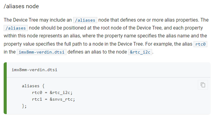
A source-level form commonly looks like:
/ {
        aliases {
                serial0 = &main_uart0;
                ethernet0 = &cpsw_port1;
        };
};
Conceptually, the alias refers to the full path of the target node. The label form is concise and resilient when the hierarchy is difficult to read, provided the referenced label is stable.
Aliases are not a substitute for a correct compatible, a valid pin mux, or a working serial-console kernel argument. They provide a consistent naming reference for firmware and software that consults them.
/chosen: values supplied by firmware for this boot
/chosen represents neither a physical component nor a permanent board wiring decision. It carries parameters selected by firmware at boot time.
/ {
        chosen {
                bootargs = "console=ttyS2,115200n8 root=/dev/mmcblk0p2 rw";
                stdout-path = "serial0:115200n8";
        };
};
The two important properties are:
bootargs: a kernel command-line string. In many U-Boot boot flows, U-Boot populates or replaces it from itsbootargsenvironment variable.stdout-path: identifies the firmware-selected console device. It may use an alias and may include serial settings after a colon.
For the boot flow from the previous lesson, remember the separation of responsibilities:
bootargsin U-Boot is the usual operational source of the Linux command line.- The DTB’s
/chosennode can carry boot arguments and a console path. - The actual usable console still depends on the correct UART node, clocks, pinmux, and kernel driver.
3. Device Node Requirements — Devicetree Specification unknown-rev documentation
Read the formal definitions of the two root-level coordination nodes. They clarify why aliases refer to paths and why /chosen is firmware-provided boot context rather than a hardware device.
In Section 3.3, read the aliases definition, including the example immediately below it. Then read Section 3.6 from the chosen-node description. Pay particular attention to the fact that stdout-path may use an alias and may include settings following a colon.
Pin control: connect the peripheral to the package pin
A peripheral controller being enabled does not automatically connect its signals to board pins. Modern SoCs expose more possible functions than they have physical pads. A pad multiplexer selects the function carried by each pad, while associated electrical settings configure details such as pull direction, input enablement, drive strength, slew rate, and voltage domain where supported.
On AM62x, pin control is normally expressed in a pin-controller node using TI-specific macros and binding-defined pad configuration values. A consumer then selects one of the defined pin states.
The general pattern is:
&pin_controller {
        gateway_uart_pins: gateway-uart-pins {
                pinctrl-single,pins = <
                        /* Binding-defined pad offset and configuration values */
                >;
        };
};

&main_uart0 {
        pinctrl-names = "default";
        pinctrl-0 = <&gateway_uart_pins>;
        status = "okay";
};
The important relationship is not the exact macro syntax. It is the separation of concerns:
gateway_uart_pinsis a pin state describing pad mux and electrical settings.pinctrl-0is a phandle reference from the UART consumer to that state.pinctrl-names = "default"names state zero.- The UART node’s
statusenables use of the peripheral after its pins are assigned.
A device may define more than one state:
pinctrl-names = "default", "sleep";
pinctrl-0 = <&gateway_can_active_pins>;
pinctrl-1 = <&gateway_can_sleep_pins>;
The binding and driver determine when each state is selected. This is particularly relevant to an automotive gateway, where a sleep state may prevent leakage or avoid driving a bus while the device is inactive.
Pinmux conflicts are hardware conflicts
Pinmux is not merely a software preference. One pad cannot simultaneously serve incompatible functions. If a pad is wired to QSPI flash and repurposed for GPIO, disabling the QSPI controller may make the boot flash inaccessible. If a CAN receive pad is configured as a GPIO output, the receiver signal cannot reach the CAN controller.
Before altering pinctrl:
- Identify the physical pad in the board schematic.
- Verify its allowed mux modes in the AM62x technical reference material and pin-mux documentation.
- Identify existing consumers of that pad in the final board DTS.
- Confirm the required direction and electrical configuration.
- Check whether disabling the previous function disconnects boot media, debug UART, Ethernet management, or another required feature.
Adding a LED to the Device Tree & Pin multiplexing
Watch Johannes 4GNU_Linux’s AM62x-focused pin-multiplexing walkthrough. Its LED example is less important than the method: trace a physical pad, choose a legal mux mode, define a pin-control state, and identify the peripheral that previously owned the pad.
Watch AM62x pin mux to see why one physical pad has several alternate functions. Then watch pinctrl ownership. Notice the risk demonstrated near the end: disabling a default OSPI function may make its attached flash unusable. Apply the same caution to boot media, debug UART, and gateway communication interfaces.
A disciplined modification workflow
For the AM62x gateway project, use the following workflow whenever you enable or add a hardware feature. It scales better than editing a DTS until the build succeeds.
1. Start from the running artifact and board evidence
Record:
- the board revision and connected peripheral;
- the vendor reference DTB filename used by U-Boot;
- the corresponding DTS source path and kernel revision;
- the relevant schematic nets and connector pins;
- a baseline serial log from the known-good reference image.
This protects against a common trap: editing a source file that is not the DTS used to generate the DTB that U-Boot actually loads.
2. Locate the existing controller and its labels
Search by function, label, compatible string, or base address:
grep -RIn "main_uart0" arch/arm64/boot/dts/
grep -RIn "main_mcan" arch/arm64/boot/dts/
grep -RIn 'compatible = "ti,' arch/arm64/boot/dts/
Then inspect the include chain. Your task is to determine which facts already come from the SoC layer and which belong in the board layer.
For an existing controller, preserve inherited properties unless the board hardware genuinely differs. A board usually changes:
status;pinctrl-namesandpinctrl-*;- board-attached child devices, such as an I2C sensor;
- regulators, GPIOs, reset lines, and board-specific wiring;
- aliases where stable numbering is needed.
3. Read the binding before authoring properties
The binding is the schema and design contract for a hardware type. It tells you:
- allowed
compatiblevalues; - required properties;
- phandle providers and the number of required specifier cells;
- valid child-node layout;
- examples and constraints.
Do not infer a property from an unrelated peripheral. For example, an I2C child device’s reg is normally an I2C address, while an MMIO controller’s reg describes a register range. The identical property name does not mean identical encoding.
4. Make the smallest board-level change
Suppose an SoC .dtsi already defines a disabled controller as &main_i2c1. A board-level enablement often has this form:
&main_i2c1 {
        pinctrl-names = "default";
        pinctrl-0 = <&gateway_i2c1_pins_default>;
        clock-frequency = <400000>;
        status = "okay";

        temperature-sensor@48 {
                compatible = "vendor,temperature-sensor";
                reg = <0x48>;
        };
};
This is a structural example, not a drop-in hardware definition. The sensor’s actual compatible, address, optional IRQ line, supply, and required properties must match the component datasheet and its binding.
Notice the division:
- The I2C controller inherits its base address, interrupt, and functional clocks from the SoC description.
- The board DTS assigns pads, enables the controller, selects an appropriate bus rate, and describes the sensor physically attached to it.
- The sensor child node uses the controller’s child-bus address-cell rules, so its
regis its slave address.
5. Review every reference as a graph
For each newly added phandle, trace both ends:
| Consumer property | Provider to inspect | What must agree |
|---|---|---|
clocks = <&provider ...> | Clock controller node | #clock-cells, clock identifier, flags |
interrupt-parent = <&provider> | Interrupt controller node | #interrupt-cells, interrupt specifier semantics |
pinctrl-0 = <&state> | Pin-controller state node | Correct pads, mux function, electrical configuration |
memory-region = <®ion> | /reserved-memory child | Intended reserved region and driver usage |
GPIO property such as reset-gpios | GPIO controller node | #gpio-cells, line number, polarity flags |
A source label may make a relationship look self-evident, but the provider’s cell count and binding determine whether the encoded value is valid.
6. Keep evidence suitable for a security-conscious portfolio
In the private repository, retain:
- a DTS patch;
- binding references;
- schematic excerpts subject to their license and confidentiality status;
- before-and-after DTB or runtime evidence;
- serial logs and kernel probe messages;
- a short rationale for pin choices and conflict checks.
In the public showcase, publish a sanitized hardware-architecture diagram, a representative DTS fragment with non-sensitive identifiers, and an explanation of the verification approach. Do not publish proprietary schematics, production flash layouts, credentials, signing material, or sensitive recovery details.
A practical reading checklist
When you encounter an unfamiliar Device Tree node, inspect it in this order:
-
Path and parent
What bus contains this node? Does the parent define#address-cellsand#size-cells? -
Node name and unit address
Does the@unit-addressagree with the first address inregwhere applicable? -
compatible
Which binding and driver family define this node? -
reg
Is it an MMIO range, I2C address, SPI chip select, or another bus-specific identifier? -
status
Is the hardware intended to be used on this board? -
Clocks and resets
Which providers does the peripheral depend upon? How many specifier cells are required? -
Interrupts
Which controller interprets them, and what trigger or polarity is specified? -
Pin control
Which pin state does the consumer request? Are the physical pads legal and uncontested? -
Child devices
Does this node contain board-attached devices, and does each child follow its own binding? -
Aliases and chosen context
Does the platform assign stable device names or a firmware-selected console path that affects boot behavior?
Key takeaways
A Device Tree is a topology contract linking silicon, board wiring, firmware, and Linux drivers.
compatibleidentifies the device programming model used for driver matching.regis interpreted by the parent bus; it may be an MMIO range, an I2C address, or an SPI chip-select.interruptsandclocksare provider-defined encodings, not generic numeric fields to guess.- Labels and phandles express graph relationships between consumers and providers.
/aliasesgives stable shorthand names for device paths, while/chosencarries boot-time firmware context such asbootargsandstdout-path.pinctrlbinds a device to legal physical pads and their electrical settings; a pinmux edit can disable boot media, debug access, or an existing interface.- Board DTS files should make focused hardware-specific changes on top of shared SoC
.dtsidescriptions.
Next, you will compile, decompile, and validate a DTB, then deliberately resolve a schema, address-cell, or phandle error.
Can't find a good explanation? Sign up and we'll make it for you
Sign up