
Welcome to the first module of the course. Before deriving transfer functions or calculating cutoff frequencies, we need to be able to read a filter circuit unambiguously. A passive filter is not identified solely by having an , , or : the location and polarity of the output measurement are equally important.
In this lesson, you will establish a reliable method for interpreting standard RC, RL, and series-RLC filter schematics. By the end, you should be able to identify the input port, output port, voltage reference polarity, and the component—or combination of components—across which is defined.
A filter schematic describes a voltage ratio
A filter is a two-port network placed between a source and a load or measurement point. Its basic quantity is the voltage transfer ratio:
For now, the important point is not how to manipulate this expression, but how the schematic tells us what its two voltages mean.
- is the voltage measured across the input terminals.
- is the voltage measured across the output terminals.
- Each voltage is defined by a positive terminal and a negative/reference terminal.
A circuit can contain the same components in the same series order yet realize different filters solely because is measured in a different place. In other words, the output is a voltage across two nodes, not merely “the voltage at a node.”
For a source referenced to a bottom conductor, we commonly write
If the output node is likewise measured relative to that bottom conductor, then
The bottom line is often drawn with a ground symbol, but the ground symbol does not itself create an output voltage. It simply declares the reference node against which the labelled voltage is measured.
A four-step protocol for reading any filter
Before deciding whether a circuit is low-pass, high-pass, bandpass, or bandreject, read it in this order.
-
Locate the input port.
Find the two terminals connected to the source or labelled , , or “input.” Identify its and markings if shown. -
Locate the output port.
Find the two terminals labelled , , or connected to a measurement/load. Trace both terminals back to circuit nodes. -
State exactly what voltage is measured.
Say “the output is across the capacitor,” “across the resistor,” “across the inductor,” or “across the series combination.” This is more precise than saying “the output is on the right.” -
Read the polarity.
The voltage label meansA polarity reversal changes the sign of the transfer function:
That changes phase by , though it does not change the magnitude response . Thus, it does not change whether a circuit has low-pass, high-pass, bandpass, or bandreject magnitude behavior.
When no and signs are drawn, a conventional interpretation is often that the labelled output node is positive with respect to the reference conductor. In formal work, however, always make the polarity explicit yourself.
Seeing the output as a pair of terminals
The schematic assortment below is useful because it shows several passive topologies with separate input and output terminal pairs. The key visual pattern is that the lower conductor often acts as the shared reference, while the output is measured from the upper output node down to that reference.
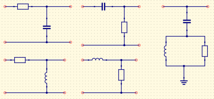
Consider the familiar RC low-pass arrangement: a resistor lies in series with the signal path, and a capacitor connects from the output node to the reference conductor. The capacitor and the output terminals share the same two nodes. Therefore,
The output is across the capacitor. The fact that a load might also connect between those same two nodes does not alter that statement: parallel elements have the same voltage.
The All About Circuits tutorial presents this topology as both a filter and a frequency-dependent voltage divider.
What Is a Low Pass Filter? A Tutorial on the Basics of Passive RC Filters
Read the opening of the “RC Low-Pass Filter” section in this All About Circuits tutorial to connect the physical drawing to the voltage-divider viewpoint used throughout passive-filter analysis.
In the section “The RC Low-Pass Filter,” begin at “As you can see in the diagram” and read through the explanation that the circuit is a frequency-dependent voltage divider. Focus on why the capacitor, load, and output terminals are in parallel: they share the same two nodes and hence the same output voltage.
A useful node-based check is this: if you can place the two probes of an ideal voltmeter directly across a component without moving either probe to a different node, then the meter reads that component’s voltage.
RC and RL: same two components, different output choices
A series RC or RL network contains two element voltages. Kirchhoff’s voltage law gives
for a series RC network, and
for a series RL network.
Which term becomes is determined by the two output terminals. This is the feature to inspect first.
| Series network | Where is measured | Standard filter response |
|---|---|---|
| RC | Across | Low-pass |
| RC | Across | High-pass |
| RL | Across | Low-pass |
| RL | Across | High-pass |
The table is worth understanding, not merely memorizing. Use extreme-frequency equivalents:
- At very low frequency, a capacitor approaches an open circuit and an inductor approaches a short circuit.
- At very high frequency, a capacitor approaches a short circuit and an inductor approaches an open circuit.
For example, take a series RL circuit. If the output is across , then at low frequency the inductor is nearly a short circuit, so almost all input voltage appears across . At high frequency, the inductor has large impedance and the resistor voltage becomes small. Thus the output across is low-pass.
If is instead across , the same circuit has the complementary high-pass response. The components did not change; the measurement definition changed.
The following short video segments are a visual check of all four first-order schematics. Watch for the two points used to label each output voltage rather than focusing only on component placement.
Low Pass Filters and High Pass Filters - RC and RL Circuits
In “Low Pass Filters and High Pass Filters – RC and RL Circuits,” The Organic Chemistry Tutor draws the standard RC and RL filter layouts and explicitly identifies the output measurement locations.
Watch RC low-pass to see the output placed across the capacitor. Then view RL low-pass, where the output is across the resistor. Compare that with RC high-pass, whose output is across the resistor, and RL high-pass, whose output is across the inductor. Pause after each drawing and identify the positive and negative measurement nodes aloud.
A schematic-reading example
Suppose a source drives a series capacitor followed by a resistor connected to the reference conductor. The output terminals are drawn across the resistor, with at the resistor’s upper terminal and at the reference conductor.
Your interpretation should be written as:
The capacitor is in series with the input path, but it is not the output component. This is the standard RC high-pass topology.
A common error is to call a circuit “an RC low-pass filter” merely because it contains a resistor and capacitor in a familiar arrangement. Instead, make the complete statement:
“This is a series RC network with output measured across ; therefore it is the standard RC low-pass topology.”
That wording forces you to distinguish the topology from the voltage measurement.
Interpreting a series RLC schematic
A series RLC circuit adds a third component, but the reading method remains exactly the same. With , , and in series,
At resonance, the inductor and capacitor voltages cancel in their phasor sum:
Therefore,
This has two important, complementary consequences.
Output across : bandpass
When , the series RLC circuit produces a standard bandpass response. At resonance, current is largest, so the resistor voltage is largest. Far below or far above resonance, the series impedance increases and current falls, reducing .
Output across the series pair: bandreject
When the output is defined from the input-side terminal of to the far terminal of , it spans both reactive elements:
At resonance, and cancel, so the voltage across the combined section is zero. The output has a notch at the resonant frequency, giving a standard bandreject response.

The image makes a crucial point: the bandpass and bandreject outputs are taken from different pairs of nodes in the same series RLC loop.
| Output definition | What the output terminals span | Response type |
|---|---|---|
| Resistor only | Bandpass | |
| Series inductor and capacitor together | Bandreject |
Notice that “across ” does not mean and are physically in parallel. Here it means the voltmeter’s terminals enclose the series combination of and , including their intermediate node.
A compact annotation habit
When you encounter a filter schematic in an assignment, redraw it quickly with four annotations:
- Write beside the two input terminals and mark and .
- Write beside the two output terminals and mark and .
- Draw a light bracket or highlight around the element(s) that lie directly between the output terminals.
- State the measurement in an equation, such as
or
or
This habit prevents several recurring mistakes:
- treating a labelled output node as a complete voltage definition;
- overlooking a reversed polarity;
- confusing a shunt component with a series component;
- assuming the filter type from the component list rather than from the output measurement;
- mistaking an RLC bandreject output across series for a voltage across a parallel branch.
Key takeaways
A passive-filter schematic must be interpreted as a specification of two voltages and their reference polarities:
To read it reliably, identify the input terminals, output terminals, and polarity markings, and the exact component or component combination across which is measured.
For the standard first-order circuits:
- RC low-pass: output across
- RC high-pass: output across
- RL low-pass: output across
- RL high-pass: output across
For the standard series RLC circuits:
- output across : bandpass
- output across the combined series : bandreject
Next, we will turn these schematic definitions into mathematics: distinguishing the symbolic transfer function from its frequency response , and evaluating that response at a specified angular frequency.
Can't find a good explanation? Sign up and we'll make it for you
Sign up