
Welcome back. In the previous lesson, you used Wireshark filters to reduce a capture from “everything observed here” to a particular protocol, service, or TCP conversation. That filtering discipline now pays off: once the relevant frame is selected, the first protocol tree item usually tells you how it was delivered on the local Ethernet segment.
This lesson focuses on reading an Ethernet II frame accurately. You will identify the local destination and sender, determine what protocol the payload contains, recognize when a VLAN tag changes the layout, and understand what the FCS can—and usually cannot—tell you from a host-based capture. These are small fields, but they are the foundation for interpreting ARP, VLANs, IPv4, IPv6, LLDP, 802.1X, MACsec, and many later protocols.
The Ethernet envelope: local delivery, not end-to-end identity
An Ethernet frame is the Layer 2 envelope used to move data across one Ethernet link or switched LAN. Its addresses are meaningful only on that local Layer 2 domain.
For an IP packet travelling from a workstation through a default gateway to a remote server:
- The workstation initially sends a frame whose destination MAC is the default gateway’s interface MAC.
- The gateway removes that Ethernet frame, makes a Layer 3 forwarding decision, and creates a new Ethernet frame for its next outbound link.
- The remote server’s MAC address is therefore not normally visible in the initial LAN frame.
This distinction prevents a common packet-analysis error: treating the Ethernet destination as the final IP destination. The destination MAC identifies the next local recipient. The IP destination, inside the Ethernet payload, identifies the end-to-end destination.
The diagram below shows the two layouts you need to recognize immediately.
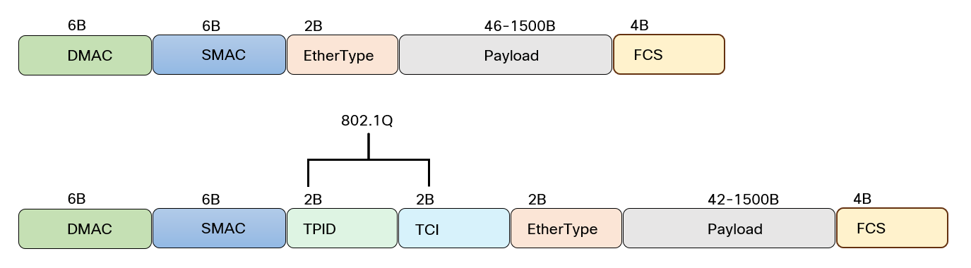
At the MAC-frame level, an untagged Ethernet II frame has this structure:
| Field | Size | Main role |
|---|---|---|
| Destination MAC | 6 bytes | Identifies the local recipient or recipient group |
| Source MAC | 6 bytes | Identifies the frame sender on this Ethernet segment |
| EtherType | 2 bytes | Identifies the protocol carried in the payload |
| Payload | 46–1500 bytes | Carries the upper-layer data, such as an IP packet or ARP message |
| FCS | 4 bytes | Allows the receiver to detect corruption in the received frame |
The basic Ethernet header is therefore 14 bytes: 6 bytes of destination MAC, 6 bytes of source MAC, and 2 bytes of EtherType.
The physical transmission also has a preamble and start-frame delimiter before the MAC frame. They help receivers synchronize to the signal, but they are normally handled by the NIC and do not appear in Wireshark. Similarly, the FCS is often checked and stripped by hardware before a frame reaches the operating system.
Reading the fields in wire order
A useful habit is to decode Ethernet in the same order a receiver does: identify the local recipient, identify the sender, determine the payload type, then hand the payload to the appropriate protocol decoder.
Destination MAC address
The first 6 bytes are the destination MAC address. A switch uses this field when deciding whether to forward, filter, or flood the frame; you will examine those decisions in the next lesson.
For now, classify the destination:
| Destination type | Example | Meaning |
|---|---|---|
| Unicast | 00:50:56:aa:bb:cc | Intended for one MAC address on the LAN |
| Broadcast | ff:ff:ff:ff:ff:ff | Delivered to every host in the broadcast domain |
| Multicast | 01:00:5e:... or 33:33:... | Delivered to interested members of a Layer 2 multicast group |
The all-ones address is Ethernet broadcast. ARP requests commonly use it because the sender knows the target IP address but does not yet know the corresponding destination MAC address.
For a multicast address, the low-order bit of the first octet is set. For example, the first octet of 01:00:5e:00:00:fb is 01, so it is a multicast MAC address. That particular address is associated with IPv4 mDNS traffic.
Source MAC address
The next 6 bytes are the source MAC address: the interface that emitted this frame onto the link.
On a client access port, it will commonly be the client NIC’s MAC. On a routed transit link, it may be the MAC address of the router or firewall interface sending the packet onward. A switch learns source MAC addresses from incoming frames, associating each learned MAC with an ingress port and VLAN.
MAC addresses are 48-bit values, conventionally shown as six hexadecimal octets. Their first portion can identify an assigned vendor block, although that should be treated as a clue rather than proof of device identity. Virtual machines, clustered services, privacy features, MAC randomization, and locally administered addresses all weaken the assumption that a MAC identifies one specific physical NIC.
The Wireshark Wiki’s Ethernet reference gives a concise on-wire view of the frame and clarifies what a capture application typically receives from the NIC.
Read the Wireshark Wiki reference to anchor the field sizes and the practical limitations of capture visibility—especially the usual absence of the preamble and FCS in Wireshark.
In the “Packet format” section, inspect the field-size table, then read the capture-visibility explanation. Next, in “MAC address fields,” focus on broadcast, multicast, and the locally administered bit. Finally, jump to “Frame Check Sequence (FCS) field” and read the FCS description. Keep separate in your notes what exists on the wire from what a normal host capture exposes.
EtherType: choosing the next decoder
The next 2 bytes in an Ethernet II frame are the EtherType. Their job is protocol demultiplexing: they tell the receiving system what decoder should receive the payload bytes.
For example, if the EtherType is 0x0800, the receiver passes the payload to the IPv4 handler. If it is 0x0806, it passes the payload to ARP instead. This is why ARP can run directly over Ethernet without IPv4 or IPv6 around it.
| EtherType | Protocol carried in the Ethernet payload |
|---|---|
0x0800 | IPv4 |
0x0806 | ARP |
0x86DD | IPv6 |
0x8100 | 802.1Q VLAN tag follows |
0x88CC | LLDP |
0x888E | 802.1X EAPOL |
0x88E5 | MACsec |
0x8847 | MPLS unicast |
Do not confuse an EtherType with a TCP or UDP port. A port identifies an application-facing transport endpoint inside an IP packet. EtherType identifies the protocol immediately inside Ethernet. For example, a DNS request normally has this nesting:
Ethernet II
  IPv4 or IPv6
    UDP or TCP
      DNS
Its Ethernet EtherType is usually IPv4 or IPv6, not “DNS.”
EtherType versus Length
Historically, the same 16-bit position after the source MAC can mean either an EtherType or a payload length. For the Ethernet II format in this lesson, it is an EtherType. The practical decoding rule is:
| Field value | Interpretation |
|---|---|
| 0 through 1500 | IEEE 802.3 Length field |
| 1501 through 1535 | Reserved / undefined |
| 1536 and above | EtherType |
In hexadecimal, 1536 is 0x0600. Thus 0x0800, 0x0806, and 0x86DD are unequivocally EtherTypes.
This distinction matters when Wireshark says Ethernet II versus IEEE 802.3 Ethernet. With Ethernet II, the payload starts immediately after EtherType. With an IEEE 802.3 Length field, the payload begins with an LLC header and may include SNAP encapsulation. Ethernet II is the dominant format for contemporary enterprise IP traffic.
Ethernet Frame Format - Learning Module | OneNoughtOne
Use this OneNoughtOne module to consolidate the Ethernet II layout, the Type/Length disambiguation rule, common EtherTypes, and the insertion point of an 802.1Q tag.
Begin with “The Disambiguation Rule: 1536 Threshold.” Read the threshold explanation, including its value table. In “Common EtherType Values,” review the IPv4, ARP, IPv6, VLAN, LLDP, 802.1X, and MACsec entries; note that the field uses network byte order, as explained in the byte-order note. Then read “Ethernet II Frame Structure with EtherType” for frame sizes and padding, followed by “VLAN Tags and Double Tagging” through the single-tag parsing logic. Focus on how a tag shifts the actual EtherType four bytes later in the frame.
Payload and padding: what Ethernet carries
The payload is everything after EtherType, up to—but not including—the FCS. It carries the complete upper-layer protocol data unit for the current hop:
- An IPv4 EtherType carries an IPv4 packet.
- An IPv6 EtherType carries an IPv6 packet.
- An ARP EtherType carries an ARP message.
- An LLDP EtherType carries an LLDP data unit directly.
- An EAPOL EtherType carries 802.1X control traffic directly.
Standard Ethernet permits a maximum payload of 1500 bytes. This familiar value is the usual Layer 2 origin of an IP interface MTU of 1500 bytes.
Ethernet also requires a minimum frame size of 64 bytes, including the FCS. An untagged Ethernet II frame therefore needs at least 46 bytes after the EtherType. If the real upper-layer data is smaller, Ethernet adds padding.
An ARP message is 28 bytes, so an ordinary ARP Ethernet II frame needs 18 bytes of padding:
| Component | Bytes |
|---|---|
| Destination MAC, source MAC, EtherType | 14 |
| ARP message | 28 |
| Padding | 18 |
| FCS | 4 |
| Total | 64 |
The padding is not part of the ARP protocol. A receiver knows the meaningful ARP length from the ARP format itself and treats the surplus bytes as Ethernet padding.
802.1Q tagging: the EtherType moves, but its role does not
An 802.1Q VLAN tag is inserted between the source MAC and the original EtherType. It adds 4 bytes:
| Tag component | Size | Meaning |
|---|---|---|
| TPID | 2 bytes | Tag Protocol Identifier, normally 0x8100 |
| TCI | 2 bytes | Tag Control Information: PCP, DEI, and VLAN ID |
The tagged layout is:
| Byte offset from frame start | Field |
|---|---|
| 0–5 | Destination MAC |
| 6–11 | Source MAC |
| 12–13 | TPID, normally 0x8100 |
| 14–15 | TCI |
| 16–17 | Inner EtherType |
| 18 onward | Payload |
| Final 4 bytes | FCS |
The TPID tells the receiver that what appeared to be the usual EtherType position is actually the start of a VLAN tag. The receiver reads the TCI, then continues four bytes later to find the inner EtherType that identifies the actual payload protocol.
The 16-bit TCI is divided as follows:
| TCI component | Bits | Role |
|---|---|---|
| PCP | 3 | Priority Code Point, commonly used for Layer 2 QoS classification |
| DEI | 1 | Drop Eligible Indicator |
| VLAN ID | 12 | VLAN identifier |
Consider this tagged frame fragment:
Destination MAC: 00:50:56:aa:bb:cc
Source MAC:      00:50:56:11:22:33
TPID:            0x8100
TCI:             0xA064
Inner EtherType: 0x0800
Decode it in order:
0x8100says that an 802.1Q tag is present.0xA064begins in binary with1010.- The first three bits,
101, give PCP 5. - The next bit,
0, gives DEI 0. - The remaining 12 bits are
0x064, giving VLAN ID 100. - The inner EtherType
0x0800says the payload is IPv4.
So this is an IPv4 frame associated with VLAN 100, marked at Layer 2 with PCP 5 and not marked drop-eligible.
A single 802.1Q tag makes the maximum standard Ethernet frame 1522 bytes including FCS, rather than 1518 bytes. Its presence does not reduce the conventional maximum IP payload from 1500 bytes; it adds Layer 2 overhead around it.
At a host capture point, do not conclude that a frame was definitely untagged merely because Wireshark does not show a VLAN header. NIC VLAN offload, driver behavior, the capture point, and switch-port configuration can cause tags to be stripped before capture. Capturing on a trunk-facing SPAN or TAP is generally more reliable when the goal is to inspect on-wire VLAN tags. The next lesson will treat VLAN membership and trunk behavior in detail.
This short video provides a useful visual walkthrough of the frame field order, VLAN insertion, and the FCS role.
The Data Link Layer, MAC Addressing, and the Ethernet Frame
Watch “The Data Link Layer, MAC Addressing, and the Ethernet Frame” from danscourses to reinforce the exact field positions before you begin decoding frames in Wireshark.
Watch frame layout for the untagged Ethernet II field order and the role of EtherType. Continue with VLAN insertion, concentrating on how TPID and TCI sit before the relocated inner EtherType. Finish with FCS role for the error-detection concept. Treat the displayed frame-size arithmetic as secondary; the important skill is correctly locating and interpreting each field.
FCS: a link-integrity signal, not a security control
The Frame Check Sequence is a 4-byte cyclic redundancy check value at the end of the Ethernet frame. The sender calculates it across the protected MAC-frame contents; the receiver calculates its own value and compares the result. A mismatch means the received frame was corrupted, so the receiver discards it.
The FCS gives Ethernet strong accidental-error detection for a link. It does not provide confidentiality, authentication, or protection against an attacker who can deliberately generate a new valid FCS. Those are different security properties addressed by mechanisms such as MACsec, IPsec, and TLS later in the course.
In practice, you often will not see FCS values in Wireshark:
- NIC hardware normally validates the FCS before delivering a frame to the host.
- Corrupted frames are usually discarded before capture.
- Drivers often strip the valid FCS from the packet presented to the OS.
Consequently, Ethernet CRC/FCS counters on switches, routers, firewalls, and NICs are often more useful than a normal host capture when investigating physical faults, damaged cabling, optics issues, or interface problems. A capture that explicitly includes an FCS can show an incorrect checksum, but its absence from Wireshark is usually normal rather than evidence that FCS is missing on the wire.
A repeatable Wireshark decoding routine
When you select a frame in Wireshark, expand Ethernet II in the Packet Details pane and use this routine:
- Classify the destination MAC. Determine whether it is unicast, broadcast, or multicast. Ask which local device or group should receive it.
- Identify the source MAC. State which interface transmitted this frame on the observed link. Avoid assuming it is the original end host across routed boundaries.
- Check for a VLAN header. If Wireshark shows
802.1Q Virtual LAN, note the VLAN ID, PCP, and DEI. - Find the real EtherType. In an untagged frame it follows the source MAC; in a tagged frame it follows the TCI.
- Verify the next protocol.
0x0800should lead to IPv4,0x86DDto IPv6, and0x0806to ARP. If the decoded protocol does not fit the EtherType, investigate malformed traffic, a capture artifact, or a dissector issue. - Check whether FCS is available. If not displayed, record that it was not captured rather than treating it as an error.
For a brief EVE-NG or workstation observation, capture a ping, an ARP exchange, and any IPv6 traffic available on a test segment. In Wireshark, compare the Ethernet II sections of each frame. You should be able to explain why an ARP request uses broadcast, why an ICMP echo normally uses a unicast destination MAC after resolution, and why IPv6 traffic has EtherType 0x86DD. If a tagged observation point is available, add vlan as a display filter and inspect TPID, PCP, DEI, and VLAN ID directly.
Key takeaways
- Ethernet II begins with a 6-byte destination MAC and 6-byte source MAC. They describe local, hop-by-hop delivery on the observed Ethernet segment.
- The 2-byte EtherType identifies the protocol contained in the payload. The most important values to recognize are
0x0800for IPv4,0x0806for ARP, and0x86DDfor IPv6. - A value from 0 through 1500 in the Type/Length position indicates an IEEE 802.3 Length field, not an Ethernet II EtherType. Values from
0x0600upward are EtherTypes. - The Ethernet payload carries the full next protocol data unit and may include padding to meet the 64-byte minimum frame size.
- An 802.1Q tag adds TPID and TCI between source MAC and the inner EtherType. TCI contains PCP, DEI, and the 12-bit VLAN ID.
- The 4-byte FCS detects accidental transmission corruption. It is normally checked and stripped by NIC hardware, so a typical Wireshark capture does not show it.
- Correct Ethernet decoding begins with field position. In a tagged frame, the protocol-identifying EtherType is four bytes later than it is in an untagged frame.
Next, you will use destination and source MAC addresses operationally: predicting whether a switch forwards, filters, or floods a frame from the contents of its MAC address table.
Can't find a good explanation? Sign up and we'll make it for you
Sign up