
Hello, and welcome to the first module of your network-and-security architecture course. We begin with the model that lets you make sense of every packet capture, forwarding decision, tunnel, and security-policy log you will encounter: the layered view of communication.
You have worked with enterprise networking technologies, but this lesson deliberately rebuilds the foundation in a precise way. By the end, you should be able to look at a flow between two hosts, identify its headers at each layer, and explain which headers remain stable end to end versus which are rebuilt at every hop.
Models are maps, not packet formats
The OSI model and TCP/IP model organize networking functions into layers. They are not specifications stating that every packet must contain exactly seven separate headers. Rather, they give us a disciplined vocabulary for asking:
- What information identifies the application or service?
- What information identifies the process on a host?
- What information identifies the end hosts?
- What information identifies the next device on the local link?
- How is the data physically represented?
The practical TCP/IP stack is usually shown with four layers, while operational discussions often use OSI layer numbers:
| OSI model | TCP/IP model | Typical concerns and examples |
|---|---|---|
| Layer 7: Application | Application | HTTP, DNS, SSH, SMTP |
| Layer 6: Presentation | Application | Encryption, encoding, compression; TLS is commonly discussed here conceptually |
| Layer 5: Session | Application | Dialog and session management |
| Layer 4: Transport | Transport | TCP, UDP, QUIC over UDP |
| Layer 3: Network | Internet | IPv4, IPv6, routing |
| Layer 2: Data Link | Link / Network Access | Ethernet, MAC addressing, VLANs |
| Layer 1: Physical | Link / Network Access | Copper signals, fiber light, radio waves |
In real architecture conversations, OSI terminology is especially useful:
- A Layer 2 issue normally means Ethernet, VLAN, MAC-learning, or switching behavior.
- A Layer 3 issue means IP addressing, routing, MTU, or forwarding.
- A Layer 4 issue means TCP or UDP behavior, ports, or state.
- A Layer 7 issue means the service or application protocol itself.
The important mapping detail is that TCP/IP combines OSI Layers 5 through 7 into its Application layer and commonly groups OSI Layers 1 and 2 into its Link layer. Therefore, when someone says “Layer 2,” clarify mentally that they almost always mean OSI Layer 2, not the second layer of a four-layer TCP/IP diagram.
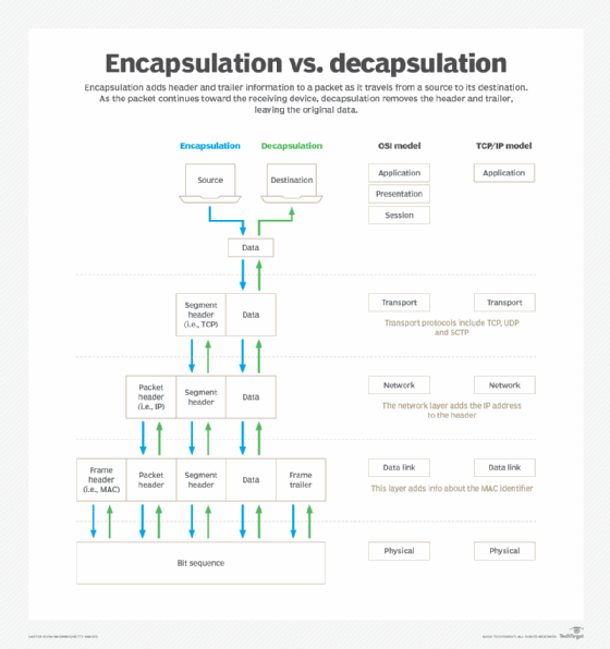
Encapsulation: building a transmittable unit
Suppose a browser sends an HTTPS request to an internal application. The useful content begins at the upper layers: an HTTP request, normally protected by TLS. To transmit it, each lower layer contributes control information appropriate to its scope.
For an IPv4 TCP flow carried over Ethernet, the on-the-wire structure can be represented as:
Each wrapper has a different job:
| Layer | Example protocol | Information added | Main scope |
|---|---|---|---|
| Application | HTTP, DNS, SSH | Service-specific commands and data | Application to application |
| Transport | TCP | Source and destination ports, sequence and acknowledgment information, flags, checksum | Process to process |
| Network | IPv4 | Source and destination IP addresses, TTL, protocol field | Host to host across routed networks |
| Data Link | Ethernet II | Source and destination MAC addresses, EtherType, optional VLAN tag, FCS trailer | One local link or Ethernet segment |
| Physical | Ethernet PHY, Wi-Fi radio | Signals representing bits | One physical medium |
The names for these units are protocol data units, or PDUs:
- At Layer 4, TCP data is usually called a segment. UDP data is often called a datagram.
- At Layer 3, it is an IP packet.
- At Layer 2, it is an Ethernet frame.
- At Layer 1, it is a stream of bits represented as electrical, optical, or radio signals.
One useful correction to a common oversimplification: lower layers do not necessarily add only a header. Ethernet adds both a header and a trailer. The Frame Check Sequence, or FCS, is a trailer used to detect corruption on a link.
TCP/IP Model: PDUs and Encapsulation & Decapsulation
Watch “TCP/IP Model: PDUs and Encapsulation & Decapsulation” from David Bombal Tech for a compact visual treatment of the wrappers, their removal at the receiver, and the fields that hand data to the next protocol.
Watch encapsulation to see application data become a Layer 4 segment, Layer 3 packet, and Layer 2 frame. Then watch decapsulation, focusing on how Ethernet, IP, and TCP are processed in turn at a receiving host. Finish with protocol handoff for the relationship among EtherType, the IP Protocol field, and TCP or UDP ports.
A concrete header stack
Consider this simplified flow:
- Client IP:
10.10.10.10 - Client default gateway:
10.10.10.1 - Application server IP:
172.20.30.40 - Application: HTTPS over TCP port 443
- The server is on a different subnet, so the client must send the first Ethernet frame to its default gateway.
On the client’s first Ethernet link, the transmitted frame is conceptually:
| Outer to inner | Example field or data |
|---|---|
| Ethernet destination MAC | MAC address of the default-gateway interface, not the remote server |
| Ethernet source MAC | Client NIC MAC address |
| Optional 802.1Q tag | VLAN ID, if the client link is tagged |
| EtherType | 0x0800, indicating IPv4 |
| IPv4 header | Source 10.10.10.10, destination 172.20.30.40, protocol 6 for TCP |
| TCP header | Ephemeral client source port, destination port 443 |
| TLS records | Handshake or encrypted application content |
| HTTP request | Usually encrypted inside TLS after handshake completion |
| Ethernet FCS | Integrity check for this Ethernet transmission |
Read that stack from the outside inward. A device must first understand the wrapper currently visible to it before it can reliably process the enclosed data.
This also explains protocol demultiplexing at the receiving host:
- The NIC receives a frame addressed to its MAC address, a broadcast address, or an address it is configured to accept.
- The EtherType identifies the payload protocol, such as IPv4 or IPv6.
- IPv4’s Protocol field identifies the next handler, such as TCP (
6) or UDP (17). - TCP or UDP destination port identifies the local service or socket.
Thus, destination MAC, destination IP, and destination port are not interchangeable “addresses.” Each answers a distinct question at a distinct scope:
| Field | Question answered |
|---|---|
| Destination MAC address | Which interface should receive this frame on this local link? |
| Destination IP address | Which end host is the intended IP destination? |
| Destination TCP or UDP port | Which process or service on that host should receive the data? |
For security analysis, this distinction is foundational. A firewall rule that permits TCP destination port 443 is making a Layer 4 decision. A switch port-security event concerns Layer 2 identity. A route lookup concerns Layer 3. Modern security devices may inspect several layers, but the underlying fields retain their separate meanings.
What changes at a switch, router, and endpoint?
The phrase “end-to-end flow” can obscure a crucial reality: not every part of a packet is end-to-end.
Imagine this path:
Client — Access Switch — Router A — Router B — Server
The client and server are endpoints. The switch and routers are intermediate devices, but they do not all process the same layers.
At the source host
The source host encapsulates from the application downward:
- The application stack creates data, such as an HTTP request within a TLS session.
- TCP adds a transport header, including ports and sequencing information.
- IPv4 adds an IP header, including source and destination IP addresses.
- Ethernet adds a local-link header and an FCS trailer.
- The NIC transmits the resulting bits across the medium.
At this point, the source host has created a frame addressed to its next hop. If the destination is remote, that next hop is normally the default gateway.
At a Layer 2 switch
A conventional switch examines the Ethernet frame primarily at Layer 2. It uses the destination MAC address and its MAC address table to decide the egress port.
For ordinary switching within the same VLAN:
- The switch does not replace the client and destination MAC addresses.
- It does not route based on the IP addresses.
- It does not remove the IP or TCP header to make its forwarding decision.
- It checks the received frame for integrity and emits a new physical transmission on the selected egress interface. The FCS is checked on receipt and regenerated for transmission.
A switch can inspect higher-layer fields for special features such as QoS classification, ACLs, telemetry, or security enforcement. But its basic forwarding identity remains Layer 2: it forwards frames based on MAC addresses.
At a router
A router receives an Ethernet frame whose destination MAC is its own interface MAC. It processes the frame sufficiently to remove the Layer 2 encapsulation and expose the IP packet.
At Router A:
- Router A receives the Ethernet frame sent by the client.
- It validates and removes the ingress Ethernet header and trailer.
- It examines the destination IP address and performs a route lookup.
- It updates certain Layer 3 fields. Most notably, it decrements the IPv4 TTL by one; because of that change, it recomputes the IPv4 header checksum.
- It determines the outgoing interface and the next-hop Layer 2 address.
- It creates a new Layer 2 frame appropriate to the outgoing link.
On an Ethernet egress link from Router A to Router B, the new frame has:
- Source MAC: Router A’s outgoing-interface MAC
- Destination MAC: Router B’s incoming-interface MAC, assuming Router B is the next hop
- Payload: the forwarded IP packet, with its decremented TTL
The Layer 2 wrapper is therefore hop by hop. It is discarded and rebuilt at every routed boundary.
By contrast, the IP source and destination addresses ordinarily identify the same endpoints for the whole routed path. “Ordinarily” matters: NAT, proxies, load balancers, IPsec tunnels, and security devices can deliberately alter, add, remove, or encapsulate headers. Those are important later architectural cases; the baseline routed behavior is to preserve the IP endpoints while updating forwarding-related fields such as TTL.
TCP header fields are also normally preserved across routers. A stateful firewall, NAT device, TCP proxy, or load balancer may change them, but a basic router does not need to inspect or alter TCP to forward IP.
Free CCNA | OSI Model & TCP/IP Suite | Day 3 | CCNA 200-301 Complete Course
Continue with “Free CCNA | OSI Model & TCP/IP Suite | Day 3” from Jeremy’s IT Lab. These segments clarify the OSI-to-TCP/IP mapping and, more importantly, show the different treatment of a packet at intermediate routers compared with the final destination.
Watch model mapping to consolidate how the seven-layer OSI model maps to the practical TCP/IP suite. Then watch router traversal, paying particular attention to the link-layer frame being removed and rebuilt at each router while the transport data continues toward the destination.
At the destination host
The final router emits a final Ethernet frame addressed to the server’s MAC address. The server then decapsulates upward:
- Layer 2: Ethernet verifies and removes the frame wrapper; EtherType hands the payload to IPv4.
- Layer 3: IPv4 verifies that the destination IP is local and uses Protocol
6to hand data to TCP. - Layer 4: TCP uses the destination port, such as 443, to find the listening service or established connection.
- Application stack: TLS decrypts protected records after the cryptographic session is established; HTTP is then processed by the web service.
The server sees the application data only after the lower-layer wrappers have been processed. This is decapsulation.
A reliable method for tracing headers
When reading a capture, device log, or design diagram, use this sequence rather than trying to memorize isolated protocol names.
1. State the link being observed
A capture does not show “the entire flow.” It shows the flow at a particular observation point.
For example, a packet capture on the client access port and a capture on a server access port may show:
- Different Ethernet source and destination MAC addresses.
- Different VLAN tags.
- Different FCS values, if the capture environment includes FCS.
- The same logical IP endpoints in a non-NAT design.
- A smaller IPv4 TTL at the server-side capture.
- The same TCP ports and sequence space in a simple routed flow.
This is why placing packet-capture points is an architectural decision. Capturing only at one point can make a NAT, asymmetric route, tunnel, or load-balancer issue appear mysterious.
2. Identify the outermost encapsulation
Ask: what medium or tunnel carries the packet at this point?
Examples include:
- Ethernet over a LAN
- 802.1Q-tagged Ethernet on a trunk
- Wi-Fi MAC framing on an 802.11 link
- IPsec ESP on a VPN path
- VXLAN over UDP/IP/Ethernet in a data-center fabric
For this module, start with ordinary Ethernet II framing. Later, you will extend the same method to VLANs, tunnels, MPLS, and overlay fabrics.
3. Follow each protocol’s handoff field inward
For a typical Ethernet/IPv4/TCP flow:
| Current layer | Field that identifies the next handler | Example |
|---|---|---|
| Ethernet | EtherType | 0x0800 means IPv4 |
| IPv4 | Protocol | 6 means TCP |
| TCP | Destination port | 443 commonly identifies HTTPS |
| TLS or HTTP | Protocol-defined content | TLS record or HTTP message |
This procedure turns packet analysis into a structured parse rather than an exercise in guessing.
4. Ask whether the device is forwarding or terminating
This single question prevents many troubleshooting mistakes.
| Device role | Typical header treatment |
|---|---|
| Layer 2 switch | Uses Layer 2 information; usually preserves the MAC addresses in the forwarded logical frame |
| Router | Removes inbound Layer 2 encapsulation, routes the IP packet, creates new outbound Layer 2 encapsulation |
| End host | Decapsulates through the transport layer to the application |
| NAT firewall | Routes and may rewrite IP addresses and TCP/UDP ports |
| Reverse proxy / load balancer | Often terminates a client TCP or TLS session and creates a separate server-side session |
| VPN gateway | Adds or removes an outer tunnel encapsulation, while preserving an inner packet |
A device that merely forwards traffic is different from a device that terminates a session. This distinction will recur in TLS inspection, SASE, proxies, load balancing, and VPN design.
5. Separate invariants from mutable fields
For a basic routed, non-NAT flow, use this mental model:
| Usually stable from client to server | Rebuilt or changed in transit |
|---|---|
| Application payload and protocol semantics | Ethernet source and destination MAC addresses at each routed hop |
| TCP source and destination ports | Ethernet FCS on each transmitted link |
| TCP sequence and acknowledgment space | IPv4 TTL or IPv6 Hop Limit |
| IP source and destination addresses | IPv4 header checksum, because TTL changes |
“Usually” is essential. A network-security architect should treat every claimed invariant as conditional on the service path. NAT changes IP and transport fields; proxies terminate and recreate connections; tunnels add outer headers; TLS encryption reduces what an intermediary can inspect at Layer 7.
Applying the model to a security path
Consider an enterprise user accessing a SaaS application through a secure web gateway. On the client’s local LAN, the outer packet may be:
If the endpoint establishes a tunnel to a SASE service, the local packet can instead be encapsulated in an outer tunnel. The original packet becomes an inner packet and may no longer be directly visible to intermediate underlay devices.
The same layered questions still work:
- Which IP addresses belong to the underlay outer packet?
- Which addresses belong to the original inner packet?
- Which device terminates the tunnel?
- Can the security service see encrypted TLS payload, or does it perform TLS decryption?
- Does a proxy create a separate connection from the security service to the destination?
This is why the models are more than certification material. They provide a way to locate the actual enforcement point, the true failure domain, and the correct capture location.
A useful operational habit is to annotate an end-to-end path with one row per link. For each link, record:
- The Layer 2 encapsulation and VLAN or tunnel context.
- The Layer 3 source and destination.
- The Layer 4 protocol and ports.
- Any device that rewrites, terminates, encrypts, or adds an outer wrapper.
That small discipline scales from a client-to-server LAN trace to a hybrid path spanning branch firewalls, Prisma Access, cloud transit, reverse proxies, and application subnets.
Key takeaways
- The OSI model is a seven-layer conceptual framework; the practical TCP/IP model combines OSI’s upper three layers into Application and usually combines Layers 1 and 2 into Link.
- Encapsulation adds control information as data moves down the stack; decapsulation processes and removes it as data moves upward.
- In a common Ethernet, IPv4, TCP flow, the frame contains an Ethernet header, IP header, TCP header, upper-layer data, and an Ethernet FCS trailer.
- MAC addresses identify the next receiver on a local link; IP addresses identify end hosts across networks; ports identify processes on an endpoint.
- A switch forwards primarily using Layer 2 information. A router removes the incoming Layer 2 wrapper, makes a Layer 3 forwarding decision, and builds a new Layer 2 wrapper for the next link.
- In a simple routed flow, Layer 2 headers change at routed hops, while IP endpoint addresses and TCP ports generally remain stable. TTL or Hop Limit changes at routers, and NAT, proxies, tunnels, and security devices can alter this baseline.
Next, you will use this layered foundation in Wireshark: constructing capture and display filters that isolate a specified protocol exchange.
Can't find a good explanation? Sign up and we'll make it for you
Sign up