
Welcome to Day 3 of your intensive design and manufacturing course. Over the last two days, you successfully designed a complete automotive component, from material selection and DFM analysis to producing a final, production-ready 2D drawing. That drawing represents a "released" part, a frozen design baseline.
Today, we shift from single-part design to a more complex and realistic scenario: managing changes within a multi-part assembly. In the fast-paced automotive world, designs are never truly static. Customer needs, cost pressures, and quality improvements drive constant evolution. As a lead engineer, your ability to manage these changes systematically is as crucial as your ability to design the part in the first place.
This lesson focuses on the formal process that governs these modifications. Our objective is to describe the Engineering Change Request (ECR) and Engineering Change Order (ECO) workflow and identify the roles involved in approving a change. Understanding this structured process is fundamental to maintaining control over cost, quality, and timing in a live production environment.
The Nature and Impact of Engineering Changes
An engineering change isn't just a casual update to a CAD file. Once a part design is formally released for tooling or production, any alteration must be rigorously controlled.
To start, let's establish a clear definition of an Engineering Change (EC) and understand why managing them is so critical.
[PDF] Reasons for Change Propagation: a case study in an automotive OEM
This research paper provides a formal definition of Engineering Changes and details their significant impact on a business, which justifies the need for a rigid control process.
Please read the following sections: Start with Section 1, "ENGINEERING CHANGE," to grasp the formal definition. Note that it specifically excludes early conceptual changes and focuses on alterations made after a design has been released. Continue to Section 1.2, "Detrimental effects of ECs." Pay close attention to the statistics on time, cost (the "ten times more" rule), and human resources. This context explains why the ECO process exists.
As the paper highlights, uncontrolled changes can trigger a "change propagation" effect, where one small modification causes a cascade of issues across other parts, tooling, and even different departments. A seemingly simple change to a plastic trim piece could affect its mating part, the assembly process on the factory floor, the packaging it ships in, and the supplier's molding tool. The workflow we're about to study is designed to identify and manage these downstream impacts before a change is approved.
The Language of Change: ECR, ECO, and ECN
In any automotive OEM or major supplier, you will constantly encounter three key acronyms that form the backbone of the change management process. Understanding the distinction is vital.
Engineering Change Request (ECR): For Streamlined Innovation
This article from SixSigma DSI provides a very clear and concise breakdown of the three core terms in the engineering change process.
Read the section titled "ECR vs. ECO vs. ECN: Decoding the Terms." This will clarify the purpose and sequence of each document.
To summarize the key distinction:
- ECR (Engineering Change Request): This is the proposal. It's a formal document that identifies a problem or opportunity and requests permission to make a change.
- ECO (Engineering Change Order): This is the authorization. Once an ECR is reviewed and approved by all stakeholders, it becomes an ECO. This document is the official instruction to implement the change.
- ECN (Engineering Change Notice/Note): This is the communication. After the change is implemented (e.g., drawings updated), the ECN is distributed to all affected departments (manufacturing, purchasing, quality) to inform them that the change is now active and when it takes effect (its "effectivity").
The flow is logical: You Request → You get an Order → You send a Notice.
The Workflow and the People Involved
Approving a change is not the sole decision of the design engineer. It's a collaborative process involving a cross-functional team, often called a Change Control Board (CCB) or Change Review Board. Each member evaluates the change from their area of expertise.
The flowchart below illustrates a typical workflow for a design change and, crucially, shows the different roles involved at each stage.
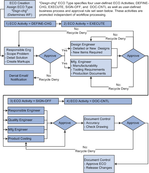
As you can see, the key players are:
- Responsible Engineer/Design Engineer: This is your role. You are the technical owner of the part. You analyze the feasibility of the proposed change, perform the design work (CAD updates, drawing revisions), and present the solution to the board.
- Manufacturing Engineer: Assesses the impact on the assembly line. Will the change require new tools, different work instructions, or affect assembly time?
- Quality Engineer: Determines how the change will be validated. Will it require a new PPAP? Do CMM programs or check fixtures need to be updated?
- Product Costing / Purchasing: Analyzes the financial impact. This includes changes to piece price, tooling investment (amortized over the part's life), and supplier logistics.
- Lead Engineer / Manager: Provides the final approval, considering the business case, resource allocation, and project timelines.
This process of review and sign-off ensures that all impacts of a change are considered before it is authorized. Denying or "recycling" a change is common if, for example, the manufacturing cost outweighs the benefit or if the technical solution is not robust.
An Automotive OEM's Process in Practice
While the flowchart above shows a generic process, real-world implementations have nuances. Automotive production lines cannot stop. This means there's often a two-track system: a fast, temporary fix to keep cars rolling, and a slower, formal process for the permanent solution.
The case study you reviewed earlier provides an excellent description of such a system.
[PDF] Reasons for Change Propagation: a case study in an automotive OEM
This paper details the practical workflow used at a major automotive OEM, including the use of temporary measures.
Read these two sections carefully: Section 3.1, "Overview of the investigation site": Focus on the paragraph describing the different online forms: ECN, ERN, substitutions, and deviations. Understanding deviations and substitutions is key to real-world practice. Section 3.2, "The EC process": Study this section and the accompanying flowchart (Fig 2). Compare this real-world process to the generic one we just discussed. Note the initial loop for an "interim solution" before moving to the "permanent engineering solution."
This dual-path approach is critical. A Deviation or Substitution is a documented, short-term, and typically limited-quantity agreement to use a part that doesn't meet the drawing specification. It's a pragmatic tool to prevent a line stoppage. For example, if a supplier has a temporary issue producing a part to the exact color specification, a deviation might be approved to accept a slightly different color for 500 vehicles to avoid shutting down the factory, while the supplier corrects their process.
This entire workflow—from request, to review, to implementation—is managed within large enterprise software platforms.
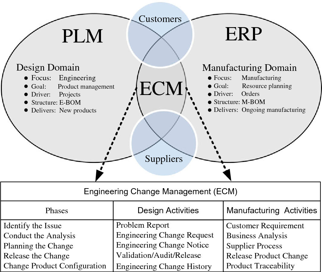
As a design engineer, you will live in the PLM system (like CATIA's ENOVIA, Siemens' Teamcenter, or PTC's Windchill). It's where you will receive your ECO, check out the relevant CAD data, perform the design change, and submit the new revisions back into the workflow for the next round of approvals.
Conclusion
In this lesson, we established the framework for managing engineering changes in a professional automotive environment. You now understand that making a change to a released part is a formal, high-stakes process governed by a clear workflow and terminology.
Key Takeaways:
- Change is Controlled: Post-release engineering changes are formally managed to mitigate significant risks to cost, timing, and quality.
- The Workflow is Key: The ECR (Request) → ECO (Order) → ECN (Notice) sequence provides a structured path from problem identification to communication of the solution.
- It's a Team Sport: Changes are approved by a cross-functional Change Control Board (CCB), where experts from design, manufacturing, quality, and purchasing all have a say.
- Reality Demands Pragmatism: Temporary deviations and substitutions are often used to keep production running while a permanent change is being implemented via the formal ECO process.
- PLM is the Arena: This entire process is orchestrated within Product Lifecycle Management (PLM) software, which serves as the single source of truth for all product data.
You have now grasped the process of engineering change. In our next lesson, we will put this knowledge into practice. You will be given a specific ECO for an interior trim assembly and tasked with interpreting it to identify the scope, rationale, and affected components.
Can't find a good explanation? Sign up and we'll make it for you
Sign up