
Welcome back. In the previous lesson, you used Kirchhoff’s Voltage Law to show that a series circuit’s resistor drops add to the supply voltage. A voltage divider is that same series-circuit idea turned into a quick calculation method.
For your exam, the key is to recognise the standard two-resistor layout, identify which resistor the requested voltage is across, and put that resistor in the numerator of the divider ratio. By the end of this lesson, you should be able to calculate an output voltage in an unloaded series voltage divider and check that the answer makes physical sense.
The standard unloaded voltage divider
A voltage divider has two resistors in series across a supply. The output is usually taken from the junction between the resistors, measured relative to the lower supply terminal.
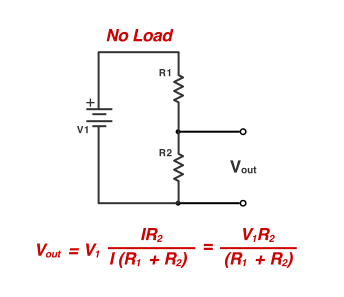
In this standard arrangement:
- is the top resistor.
- is the bottom resistor.
- is measured across .
- Both resistors carry the same circuit current, because they are in series.
- Unloaded means no device is connected across the output terminals to draw extra current.
The word unloaded matters. The usual voltage-divider formula is valid only when the output is open circuit, or when any measuring device draws such a tiny current that it can be ignored. For this lesson and for basic exam questions, “unloaded” means use the standard formula directly.
Voltage Divider Circuit Explained!
Watch “Voltage Divider Circuit Explained!” by The Organic Chemistry Tutor for a brief visual recap of the series-current method, followed by the voltage-divider shortcut.
Watch the series method to see total resistance, circuit current, and the voltage across R_2 found using Ohm’s law. Then watch the divider formula, focusing on why the resistance of the resistor across the requested output voltage is placed in the numerator.
Where the formula comes from
You do not need to re-derive the formula every time, but understanding it helps prevent the most common exam error: putting the wrong resistor in the numerator.
In the circuit shown, the total series resistance is:
The current is therefore:
The output voltage is the voltage drop across the lower resistor . Using Ohm’s law:
Substitute the current expression:
This gives the standard voltage-divider relationship:
Read that formula in words:
Output voltage equals supply voltage multiplied by the resistance of the resistor across the output, divided by the total series resistance.
The fraction is a resistance ratio. Because is only part of the total resistance, the ratio is less than . Therefore, for this standard circuit:
This also gives two quick checks:
- If , the output is half the supply voltage.
- If is much larger than , the output is close to the supply voltage.
- If is much smaller than , the output is close to .
Voltage divider (article) | Circuit analysis
Read Khan Academy’s “Voltage divider” article for a clear derivation of the formula and one fully worked example.
In the opening section, read from the introductory explanation through the derivation of the voltage-divider equation. Locate the formula explanation and make sure you can say why the lower resistor is in the numerator. Then read the section “Example - use the voltage divider equation to find v_\mathrm{out},” following the substitution, simplification of the resistance ratio, and optional current check.
A worked exam-style calculation
Question: An unloaded voltage divider has:
Calculate the output voltage across .
1. Select the formula
The output is across the lower resistor , so use:
2. Substitute all values, including units
3. Add the resistances in the denominator
Because both resistances are in , the units cancel in the ratio:
A calculator entry could be written as:
Use brackets around the whole denominator. Without brackets, a calculator may perform the operations in an order you did not intend.
4. Check using the series method
The total resistance is:
The circuit current is:
Voltage across is:
The answer agrees.
The other resistor must drop:
KVL checks the result:
The “resistor of interest” rule
Do not memorise the formula only as “put on top.” That works only when the question uses the standard layout and asks for voltage across the bottom resistor.
The more reliable rule is:
The resistor across which you want the voltage goes in the numerator.
If a question asks for voltage across the top resistor , use:
For example, with a supply, , and :
The voltage across is then:
Notice that is larger, so it has the larger voltage drop. In a series circuit, voltage divides in proportion to resistance.
Units and calculation traps
Resistances must use the same prefix before adding
This is correct because both resistor values are in :
But this is not correct:
You must first convert one value. For example:
Now the values can be added safely.
Example: A supply has and . Find the output across .
The answer is reasonable: is the larger resistor, so it receives more than half of the supply.
Avoid these common mistakes
| Mistake | Why it is wrong | Better habit |
|---|---|---|
| Using in the numerator when the output is across | It calculates the voltage across the wrong resistor. | Circle the requested resistor before writing the formula. |
| Forgetting to add both resistors in the denominator | The current depends on the total series resistance. | Write the denominator brackets first: . |
| Adding and directly | The values represent different sized units. | Convert to matching prefixes before adding. |
| Giving an output larger than the supply | An unloaded two-resistor divider cannot increase voltage. | Check that . |
| Assuming the junction is always half the supply voltage | Half supply occurs only when the two resistors are equal. | Compare the resistor ratio. |
An exam routine you can repeat
For a basic unloaded voltage-divider question, use this layout:
- Identify the supply voltage and the two series resistance values.
- Mark which resistor has the requested voltage across it.
- Ensure resistance units match before adding them.
- Write the divider relationship with the requested resistor in the numerator.
- Substitute values with brackets around the total resistance.
- Calculate and state the answer in volts.
- Check reasonableness: the two voltage drops must add to the supply voltage, and the larger series resistor should have the larger drop.
For the usual lower-resistor output arrangement, your method-mark working should look like:
Key takeaways
A voltage divider is an unloaded series circuit that produces a chosen fraction of the supply voltage across one resistor.
For output measured across the lower resistor :
Remember these three rules:
- The two resistors are in series, so they carry the same current.
- Put the resistor across the required voltage in the numerator.
- Use matching resistance units before adding values in the denominator.
This formula is a shortcut built from Ohm’s law and the KVL relationship you used previously. Next, you will move from one current path to multiple paths by calculating total resistance and branch currents in parallel circuits.
Can't find a good explanation? Sign up and we'll make it for you
Sign up