
Welcome back. Your scene already contains the beginnings of a greybox: a floor, a pillar, an angled barrier, and a marker. Those shapes establish visible space. Today you will turn that space into a test room that can support later player-movement experiments.
A useful distinction: a greybox is not merely a rough-looking level. It is a design instrument. Its job is to let you test questions such as “Does this corridor feel too narrow?” and “Does this barrier clearly block the intended route?” before spending time on art.
By the end of this lesson, Core Escape Greybox will contain a solid floor, enclosing walls, static obstacles, and a falling physics probe that confirms collision is working.
From visible geometry to solid game space
In the last lesson, you changed an entity’s transform to determine where it appears. Physics adds a second layer: the invisible shape that determines how an object behaves when something touches it.
There are three relevant pieces:
| Piece | Purpose | Example in your test room |
|---|---|---|
| Render component | Makes an object visible. | The green floor box you can see. |
| Collision component | Defines an invisible physical volume. | The box-shaped boundary that matches the floor. |
| Rigid Body component | Makes that collision volume take part in physics. | A floor that stops a falling object. |
A Collision component by itself is a trigger: it can detect an object entering its volume, but it does not physically stop it. To make the floor, walls, and obstacles solid, each needs both a Collision component and a Rigid Body component.
The most important rigid-body types for this course are:
- Static: an object that never moves. Use this for floors, walls, and permanent obstacles.
- Dynamic: an object affected by gravity, impacts, and forces. Use this for the temporary falling probe today.
- Kinematic: an object positioned deliberately by code. A moving platform is a typical future use.
Before building, study the short official overview. It explains why PlayCanvas needs its physics module imported and establishes the distinction between static and dynamic objects.
Physics Basics - PlayCanvas Developer Site
Read PlayCanvas's “Physics Basics” guide to understand the minimum setup behind a solid floor and a falling object.
In the “Enabling Physics” section, read the physics setup explanation. Then find the “Rigid Bodies” section and read the introduction to rigid bodies, including the Static, Dynamic, and Kinematic list immediately below it. Focus on what should move in a test and what should remain fixed.
A collision shape does not need to be as detailed as the object’s visual model. In professional production, it is usually simpler. A complex sci-fi crate might have a simple box collider; a character usually has a capsule collider. For this first test room, box colliders are ideal because your geometry is made from boxes.
The inspector image below shows the key pattern you will repeat: a Box collision shape sized with Half Extents, plus a Static rigid body.
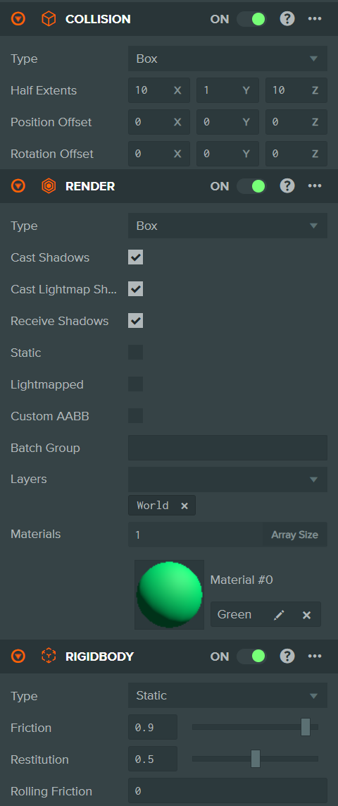
Half Extents: sizing the invisible box
For a Box collision shape, Half Extents means the distance from the object’s center to each collider edge. If the visible box is units wide, its X half extent should normally be .
For the simple box primitives used here:
So a box with Scale needs Box Half Extents of .
If the collider is smaller than the visible object, a moving body can appear to sink into it before collision occurs. If it is too large, the body can appear to hit an invisible wall before reaching the visible surface. Matching them makes your test results trustworthy.
Build the boundaries of the test room
Open Core Escape Greybox and save your work first.
1. Enable physics
Before adding any rigid bodies, enable PlayCanvas physics:
- Open Scene Settings from the editor’s settings controls.
- Find the Physics area.
- Choose Import Ammo or the equivalent button to import the physics module.
- Wait for PlayCanvas to add the Ammo asset and remove any physics-related warnings.
You only need to do this once for the project. The default gravity setting points downward along the Y axis, which is exactly what you want for today’s falling probe.
2. Reuse your transform study
Rather than throw away the work from the previous lesson, convert it into a small physics lab.
Rename Floor Guide to Test Floor and confirm these transform values:
| Entity | Position | Rotation | Scale |
|---|---|---|---|
| Test Floor |
Its top surface remains at . That is the reference surface for every upright object in the room.
Keep these previous objects where they are:
| Entity | Position | Rotation | Scale |
|---|---|---|---|
| Pillar | |||
| Angled Barrier | |||
| Core Marker |
For now, Core Marker stays visual only. It represents a future point of interest rather than an obstacle. The pillar and angled barrier will become solid.
3. Create four walls
Add four Box entities. Rename each immediately, then enter the following transform values in the Inspector.
| Entity | Position | Rotation | Scale |
|---|---|---|---|
| North Wall | |||
| South Wall | |||
| West Wall | |||
| East Wall |
The floor spans from to along both horizontal axes. Each wall’s outer surface sits at the floor’s edge, while its inner surface creates a usable room just under units across.
In a top orthographic view, you should now see:
- A square room boundary
- An angled barrier near the southeast portion of the space
- A pillar toward the southwest
- A marker toward the northeast
- A clear central area for later movement tests
At this stage, the walls are only visible walls. Launching the project would not make a dynamic object stop against them yet. The next step gives the room its physical behavior.
Add collision and static rigid bodies
For every entity in the following table, add two components through Add Component in the Inspector:
- Add Collision and choose Box as the type.
- Set the Box Half Extents values shown.
- Add Rigid Body and set its Type to Static.
Do this for Test Floor, all four walls, Pillar, and Angled Barrier.
| Entity | Collision type | Half Extents | Rigid Body type |
|---|---|---|---|
| Test Floor | Box | Static | |
| North Wall | Box | Static | |
| South Wall | Box | Static | |
| West Wall | Box | Static | |
| East Wall | Box | Static | |
| Pillar | Box | Static | |
| Angled Barrier | Box | Static |
Notice what you are not doing:
- Do not make the floor dynamic. A dynamic floor would fall under gravity.
- Do not add a rigid body to Core Marker yet. It is a visual landmark, not a blockage.
- Do not worry about making the wall corners perfectly seamless. Slight overlap between static colliders is fine for this small test room.
Use the editor’s Physics view mode after configuring a few objects. It lets you inspect collision and trigger volumes rather than trusting that the invisible shapes are aligned correctly.
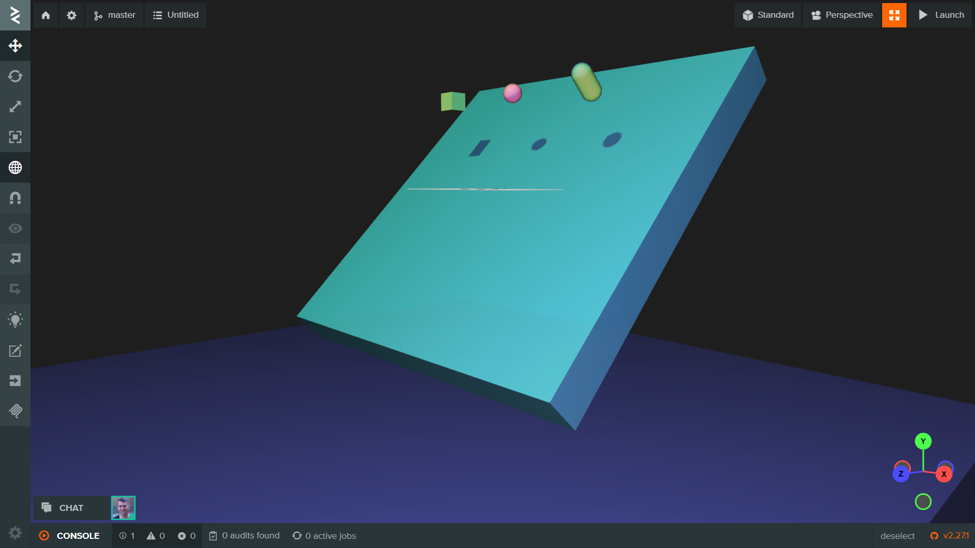
Check the Test Floor first. Its physical box should cover the full visible floor. Then inspect Angled Barrier from more than one camera angle: its collider should rotate with it and remain thin along its local Z axis.
The following video demonstrates the exact workflow of scaling a visual box, matching its collider using half extents, and assigning it a Static rigid body.
PlayCanvas Tutorial 10 - Rigid Bodies and Collision in PlayCanvas
Watch Daniel Wood's “Rigid Bodies and Collision in PlayCanvas” for a clear editor demonstration of the components you are adding.
Watch physics roles for the meaning of rigid bodies, friction, and restitution. Then watch static ground, paying close attention to why the collision half extents are half the visible box dimensions. Finish with the dynamic test to see how a Dynamic body differs from the static environment.
Add a dynamic probe and validate the room
A test room needs one object that can reveal mistakes. Create a Sphere primitive, rename it Drop Probe, and enter:
| Property | X | Y | Z |
|---|---|---|---|
| Position | 0 | 4 | -4 |
| Rotation | 0 | 0 | 0 |
| Scale | 1 | 1 | 1 |
The probe begins four units above the floor, away from the existing pillar and angled barrier.
Now add its physics components:
- Add a Collision component.
- Change Collision Type to Sphere.
- Set its Radius to , matching the one-unit-wide sphere.
- Add a Rigid Body component.
- Set Rigid Body Type to Dynamic.
- Leave mass, friction, and restitution at their initial values for this first test.
Save the scene, then launch the project. The expected behavior is simple:
- Drop Probe falls because it is Dynamic and gravity is enabled.
- It collides with Test Floor rather than passing through it.
- It may bounce briefly, depending on restitution.
- The floor, walls, pillar, and angled barrier do not move because they are Static.
You have created the smallest useful collision experiment: one active physics object interacting with a fixed environment.
Diagnose the three most common results
| What you see | Most likely cause | First thing to inspect |
|---|---|---|
| Drop Probe falls through the floor | The floor lacks a Collision or Static Rigid Body component. | Test Floor’s component list. |
| Drop Probe remains suspended in midair | Its Rigid Body type is Static, not Dynamic. | Drop Probe’s Rigid Body Type. |
| Drop Probe seems partly inside the floor | The floor collider’s Y half extent or position does not match the visible floor. | Test Floor’s and Collision Half Extent Y . |
| Probe collides before reaching a wall | A wall collider is larger than its visible box. | That wall’s half extents. |
| Probe passes visibly into a wall | A wall collider is too small, missing, or not paired with a Static Rigid Body. | Collision size and Rigid Body Type. |
Do not treat these as merely technical glitches. Each mismatch changes what a player perceives. A barrier that looks solid but can be crossed breaks the player’s trust in the level. A collider that extends beyond a wall creates an invisible obstruction. Physical clarity is part of readable game design.
Completion check
Before closing PlayCanvas, confirm that your scene has:
- A Test Floor with Box Collision and a Static Rigid Body.
- Four static walls that create a bounded room.
- A solid Pillar and Angled Barrier.
- A Core Marker that remains visual-only.
- A Drop Probe with a Sphere Collision component and a Dynamic Rigid Body.
- A probe that falls and rests on the floor when launched.
- Collision volumes that generally match the visible geometry in Physics view.
- A saved scene.
Key takeaways
A playable 3D space has both visible geometry and physical geometry. In PlayCanvas, the Collision component defines the physical volume, while the Rigid Body component determines whether that volume participates in physics as a stationary object or a moving one.
You built a compact collision lab from your earlier greybox: a static floor, perimeter walls, a pillar, an angled barrier, and a dynamic sphere to test whether the environment behaves as intended. You also used half extents to align box colliders with the dimensions of visible primitives.
Next, you will organize these entities with clear names and parent-child relationships, making the scene easier to expand, debug, and work with as the prototype becomes more complex.
Can't find a good explanation? Sign up and we'll make it for you
Sign up