
Hello! Welcome to the fourth lesson in our Statics module.
In the last lesson, you mastered the technique of applying equilibrium equations to find the external support reactions on a rigid body. That was a crucial skill because it's the mandatory first step for what we're about to do today: looking inside the structure.
Today's learning outcome is to analyze forces in simple truss structures using the method of joints and the method of sections. We'll learn how to determine the internal axial force (tension or compression) in each member of a truss. This is a vital skill in aerospace engineering, used to design the strong yet lightweight frameworks found in aircraft wings, fuselage skeletons, and support gantries.
What is a Truss?
Trusses are structures composed of slender members connected at their ends. They are incredibly efficient at spanning large distances and carrying loads. Think of bridges, roof supports, and the iconic lattice structure of crane arms.
To make the analysis of these complex structures manageable, we rely on two key assumptions. These simplifications are foundational to truss analysis.
Understanding and Analysing Trusses
This video from 'The Efficient Engineer' provides a concise introduction to trusses and the critical assumptions that simplify their analysis.
Please watch the first 2 minutes and 56 seconds of the video. Pay close attention to the two main assumptions: (1) joints are treated as pinned connections, and (2) loads are applied only at the joints.
As the video explained, these assumptions mean that every member in an ideal truss is a two-force member. This is a powerful simplification. A two-force member can only be subjected to forces at its two ends, and for it to be in equilibrium, these forces must be equal, opposite, and act along the line connecting the two points.
This means every member is either being pulled apart (in tension) or pushed together (in compression). There is no bending or shear.
This level of idealization is similar to circuit analysis in your electronics background. When you use Ohm's Law (), you treat a resistor as an ideal component, ignoring real-world complexities like parasitic capacitance or temperature effects. Similarly, by treating truss members as ideal two-force members, we can use relatively simple equilibrium equations to analyze the entire structure.
Method 1: The Method of Joints
The first technique we'll learn is the Method of Joints. The logic is simple: if the entire truss is in static equilibrium, then every single joint within it must also be in equilibrium.
We can analyze each joint as if it were a particle, with the member forces and any external loads acting on it. Since all these forces are concurrent (they pass through a single point), we only need to satisfy the force equilibrium equations:
Because we only have two equations per joint, we can only solve for a maximum of two unknown member forces at a time.
The Procedure
- Solve for Support Reactions: First, treat the entire truss as a single rigid body and find the external support reactions, just as you did in the previous lesson.
- Select a Starting Joint: Find a joint with at most two unknown forces. This is often a support joint.
- Draw the Joint's FBD: Isolate the joint and draw the FBD, showing all known external forces/reactions and the unknown forces from the members connected to it.
- Assume and Solve: A common convention is to assume all unknown member forces are in tension (pulling away from the joint). Apply the two equilibrium equations to solve for the unknowns.
- If the result is positive, your assumption was correct, and the member is in tension.
- If the result is negative, your assumption was wrong, and the member is in compression (pushing towards the joint).
- Repeat: Move to an adjacent joint that now has two or fewer unknowns and repeat the process until all member forces are found.
Let's watch a detailed worked example that walks through this entire process.
Statics: Lesson 48 - Trusses, Method of Joints
This video from Jeff Hanson provides a very clear, step-by-step application of the Method of Joints. He follows the procedure exactly as described above.
Please watch from 02:39 to 18:43. This is a comprehensive example. 02:39 - 06:31: He first finds the global support reactions (Step 1). 06:31 - 10:42: He starts with Joint A, which has two unknowns, and solves for the forces in members AD and AB (Steps 2-5). 10:42 - 16:19: He moves to Joint B, using the known force in AB to solve for members BD and BC. 16:19 - 18:43: He finishes at Joint C to find the last unknown force in member CD.
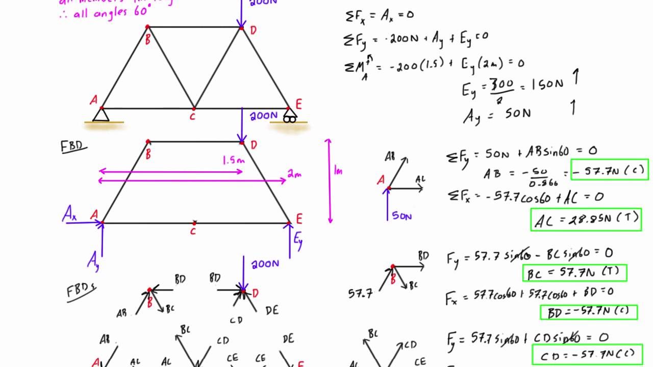
Below is an image summarizing another complete worked example. Trace through the calculations to solidify your understanding of the joint-by-joint process.
A Time-Saving Trick: Zero-Force Members
In many trusses, some members carry no load under a given loading condition. Identifying these "zero-force members" early can significantly speed up your analysis. The video from The Efficient Engineer (which you watched the start of) explains two common rules for spotting them at around the 8:50 mark. The LibreTexts resource below also formalizes these rules.
Method 2: The Method of Sections
The Method of Joints is thorough, but it can be slow if you only need the force in one specific member in the middle of a large truss. The Method of Sections is a more direct approach for this.
Instead of isolating a joint, we make an imaginary "cut" through the truss, dividing it into two separate sections. We then analyze one of these sections as a rigid body in equilibrium. This brings the moment equation back into play!
Because we now have three equations, our cut should not pass through more than three members with unknown forces.

The Procedure
- Solve for Support Reactions: This step is the same. Always find the external reactions first.
- Make a Cut: Pass an imaginary section through the members whose forces you want to find. Do not cut through more than three members.
- Draw the Section's FBD: Choose one of the two resulting sections and draw its FBD. Include all external forces, support reactions, and the unknown internal forces exposed by the cut. Again, it's conventional to assume the unknown forces are tensile.
- Apply Equilibrium Equations: Use your three equilibrium equations () to solve for the unknown forces.
A powerful strategy is to sum moments about a point where the lines of action of two of the three unknown forces intersect. This eliminates them from the moment equation, allowing you to solve for the third unknown directly.
Understanding and Analysing Trusses
Let's return to 'The Efficient Engineer' video to see a clear demonstration of the Method of Sections.
Please watch from 11:01 to 14:10. Notice how he strategically takes moments about joint F to immediately find the force in member GE, because the other two unknown forces (FD and FE) pass through F.
Test your understanding!
Look at the truss from the video you just watched (Method of Sections example). The cut was made through members FD, FE, and GE. To solve for the force in member FD (), which point would be the best choice to sum moments about? Why?
Show answer
The best point to sum moments about to find is joint E.
The other two unknown forces, and , both have lines of action that pass through joint E. Therefore, they would produce zero moment about E, leaving as the only unknown in the moment equation.
Putting It All Together
Both the Method of Joints and the Method of Sections are essential tools. To get a consolidated view of the procedures and see more worked examples, please review the following text.
This resource from LibreTexts, 'Methods of Truss Analysis', provides a formal summary of both methods, including the sign convention, procedure lists, and worked examples.
Please read through the following sections: Start with Section 5.6.2: Analysis of Trusses by Method of Joint. Review the 'Procedure for Analysis' and skim through 'Example 5.2'. Read Section 5.6.3: Zero Force Members to see the rules for identifying these members. Finally, read Section 5.6.4: Analysis of Trusses by Method of Section. Review the procedure and skim 'Example 5.3'. Focus on the step-by-step procedures outlined for each method.
Conclusion
You now have two powerful methods for analyzing the internal forces in truss structures.
Key Takeaways:
- Truss analysis is simplified by assuming pinned joints and loads applied only at joints, which makes all members two-force members (only in tension or compression).
- The first step for both methods is to find the external support reactions for the entire truss.
- Method of Joints:
- Analyzes the truss joint-by-joint using and .
- Best for finding the forces in all members of the truss.
- Can only start at a joint with a maximum of two unknowns.
- Method of Sections:
- Analyzes a section of the truss using , , and .
- Best for quickly finding the forces in a few specific members.
- The cut should not pass through more than three unknown-force members.
Next Lesson Preview:
In this lesson, we relied on the simplification that all members are two-force members. But what happens in machine linkages or frames where members are connected in more complex ways and loads are applied mid-span? In the next lesson, we will analyze forces in frames and machines with multiple connected members. This will involve disassembling the structure and analyzing each component as a general rigid body that can experience not just axial force, but also shear force and bending moment.
Can't find a good explanation? Sign up and we'll make it for you
Sign up