
Hello! Welcome to the fifth lesson in our Statics module.
In our last lesson, we mastered the analysis of trusses using the Method of Joints and the Method of Sections. The key simplification was that all members were two-force members, meaning they could only be in simple tension or compression. This assumption holds true for ideal trusses but not for many other common engineering structures.
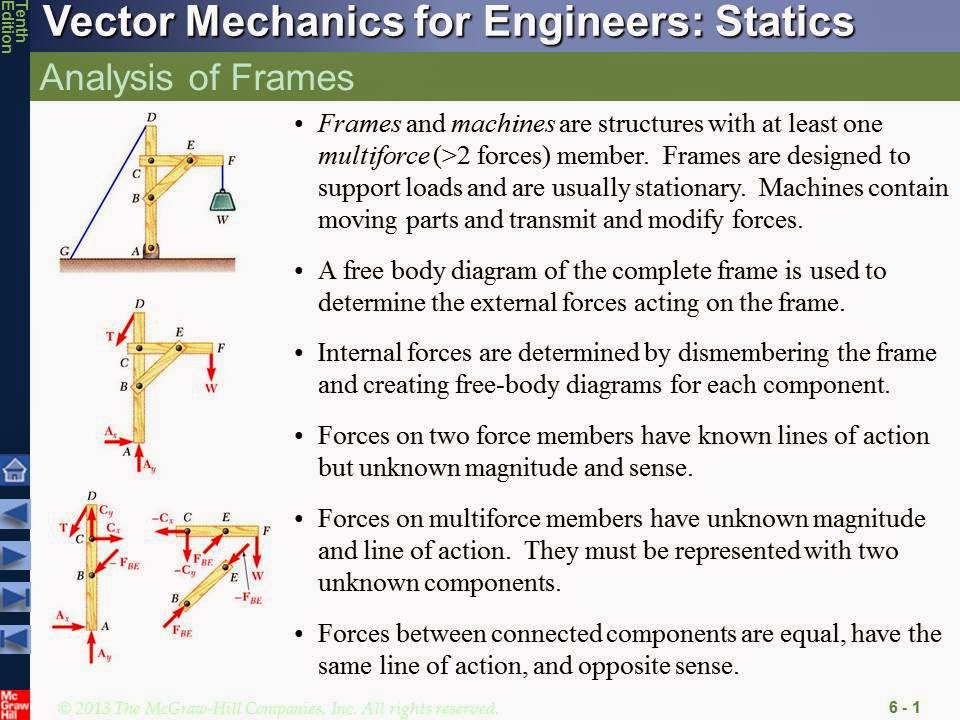
Today, we will build on those concepts to tackle more complex systems. Our learning outcome is to analyze forces in frames and machines with multiple connected members. Unlike trusses, these structures contain at least one multi-force member, which can be subjected to forces at multiple points, leading to internal shear forces and bending moments. This is a critical skill for analyzing many mechanical systems you'll encounter in aerospace, such as landing gear mechanisms, flight control linkages, and engine mounts.
From Trusses to Frames and Machines
The first step is to understand what defines a frame or a machine and how they differ from the trusses we've already studied.
- Frames are rigid, stationary structures designed to support loads.
- Machines are structures with moving parts, designed to transmit or modify forces (e.g., pliers, a car jack, or an aircraft's flap mechanism).
Despite their different purposes, the method we use to analyze them is identical. The key feature that separates them from trusses is the presence of at least one multi-force member. A multi-force member is any member that has forces applied at more than two points, or has forces that are not directed along the axis of the member.
How to solve frame and machine problems (statics)
This video from Engineer4Free provides an excellent introduction to frames and machines, highlighting the crucial difference from trusses and outlining the general analysis strategy.
Please watch the first 3 minutes and 5 seconds of the video. Focus on: The definition of a multi-force member. The distinction between stationary frames and moving machines. The high-level, two-step process for solving these problems.
The Analysis Method: Taking it Apart
As the video introduced, we can't analyze frames and machines by simply looking at the joints. The presence of multi-force members means that the forces at the connecting pins are not necessarily directed along the members. We need a more robust method, often called the Method of Members.
The core idea is to disassemble the structure and analyze each component as an individual rigid body. Your experience with circuit analysis, where you analyze a complex circuit by examining individual components and the nodes connecting them, is conceptually similar. Here, our "components" are the members and our "nodes" are the pins.
The procedure is as follows:
-
Analyze the Entire Structure: Draw a Free-Body Diagram (FBD) of the entire frame or machine as a single rigid body. If the structure is statically determinate as a whole, solve for the external support reactions using the three equilibrium equations: , , and . Often, you won't be able to find all of them, but any you can find will be helpful later.
-
Disassemble and Draw FBDs: "Explode" the structure into its individual members. Draw a separate FBD for each member, showing all applied loads, any support reactions you found in Step 1, and the unknown forces at the points where members connect (the pins).
-
Apply Newton's Third Law: For every internal pin connection, the forces on the two connecting members must be equal and opposite. If you draw the force components and acting on member 1, you must draw them with the same magnitude but in the opposite directions on member 2. This is the most critical step in keeping your analysis consistent.
-
Solve the Equations: Apply the three equilibrium equations to the FBD of each member. By systematically working through the members, you create a system of equations that allows you to solve for all the unknown pin forces.
Let's see this process put into practice.
Frames and Machines | Mechanics Statics | (Solved Examples Step by Step)
The following video from Question Solutions provides excellent step-by-step solved examples that demonstrate this procedure clearly.
Please watch the first example in the video, from 02:22 to 05:43. Pay close attention to how the analyst: First analyzes the whole frame to find the reaction at support A. Draws separate FBDs for members DBF and ABC. Represents the forces at pin B as an equal and opposite pair on the two members. Uses the moment equation strategically to solve for unknowns.
A Deeper Dive into the Procedure
The process is highly systematic, which should appeal to your preference for a formula-based approach. The key is careful bookkeeping of forces and consistent application of equilibrium equations.
This web resource provides a clear, text-based summary of the analysis procedure and an important note on why the Method of Joints fails for these structures.
Please read the following sections from the webpage: Start just after the images and read the two paragraphs that introduce the method of disassembling the structure. Continue to Subsection 6.5.2 Analysis Procedure and review the step-by-step guide. Read the 'Thinking Deeper' box at the end. It provides an excellent explanation for why we need this new method instead of the Method of Joints from our last lesson.
Example 2: Analyzing a Machine and Spotting Two-Force Members
Now, let's analyze a machine. Remember, the analysis method is the same, but the purpose of the structure is different. In this example, also notice how identifying a two-force member (just like in a truss) can simplify the problem.
Frames and Machines | Mechanics Statics | (Solved Examples Step by Step)
Let's return to the 'Question Solutions' video for another example, this time of a machine that includes a two-force member.
Watch the second example from 05:43 to 08:08. Notice how the member AB is identified as a two-force member. This allows the force at B to be represented by a single unknown magnitude, F_AB, with a known line of action, rather than two separate components Bx and By.
Test your understanding!
In the video example you just watched, why can member AB be treated as a two-force member, while member CB cannot?
Show answer
Member AB can be treated as a two-force member because it is a straight member with forces applied only at its two endpoints (pins A and B).
Member CB, on the other hand, is a multi-force member because forces are applied at more than two points: at pin C, at pin B, and from the two tension forces from the cable wrapped around the pulleys.
To consolidate your understanding, let's review one more resource that provides a detailed procedural breakdown and a well-illustrated example.
Engineering Mechanics: Chapter 6 – Equilibrium of Structures
This chapter from an open-source textbook provides another excellent, structured overview of the topic. The procedure and visual breakdown of a toggle clamp are particularly helpful.
Please read Section 6.6 – Frames and Machines. Focus on the 'Analyzing Frames and Machines Procedure'. Then, look through the series of diagrams under 'Free-body diagram of structures' showing the step-by-step 'explosion' of the toggle clamp. This visualization is a great way to understand how each part is isolated for analysis.
Conclusion
In this lesson, we moved from the idealized world of trusses to the more general cases of frames and machines. The key was learning to handle multi-force members by disassembling the structure and applying the principles of rigid body equilibrium to each part.
Key Takeaways:
- Frames and Machines contain at least one multi-force member, distinguishing them from trusses.
- The analysis procedure, the Method of Members, involves:
- Analyzing the entire structure as one rigid body to find external reactions (if possible).
- Disassembling the structure into its components.
- Drawing an FBD for each component.
- Applying Newton's Third Law at the connecting pins (forces are equal and opposite).
- Using the three equilibrium equations (, , ) on each member to find the unknown forces.
- Always be on the lookout for two-force members within a frame or machine, as they simplify the analysis.
Next Lesson Preview:
So far, all of our equilibrium problems—for particles, rigid bodies, trusses, and frames—have been in two dimensions. In the next lesson, we will apply equilibrium concepts to solve for reactions in simple 3D rigid bodies. This will involve expanding our equilibrium equations to three dimensions, a necessary step for analyzing most real-world engineering components and systems.
Can't find a good explanation? Sign up and we'll make it for you
Sign up