
Hello! Welcome to the first lesson of our course on mechanical engineering fundamentals. We're kicking things off with the first module on Statics, which is the study of objects at rest.
Today, we'll focus on the single most important tool in all of mechanics: the Free-Body Diagram (FBD). The learning outcome for this lesson is to be able to define a free-body diagram for a rigid body to identify all external forces and moments.
Mastering this skill is essential, as it's the first step in solving almost every problem in statics, dynamics, and mechanics of materials. Think of it as the equivalent of drawing a circuit diagram before analyzing voltages and currents in electronics; it's how we translate a physical situation into a solvable engineering problem. This foundation will be critical as we build towards your goal of studying aerospace engineering.
What is a Free-Body Diagram?
In physics, you've likely dealt with forces acting on a point-like particle. In engineering, we deal with rigid bodies, which are objects with size and shape. For a rigid body, it's not just the magnitude and direction of a force that matters, but also where on the body it is applied, as this can cause the body to rotate.
A Free-Body Diagram is a simplified sketch that isolates a body from its surroundings and shows all the external forces and moments acting on it.
To get a formal introduction to FBDs and their role in ensuring an object is in equilibrium (i.e., not moving or accelerating), please watch the following video.
Engineering Mechanics: Statics Lecture 7 | Free Body Diagrams
This video from Dr. Clayton Pettit provides an excellent introduction to why FBDs are essential and what they consist of.
Please watch from 05:00 to 06:39. Focus on the two essential components that every FBD must include: all forces acting on the body, and all relevant dimensions.
As the video explains, a complete FBD includes:
- A sketch of the isolated object.
- All external forces and moments acting on the object.
- All relevant dimensions and angles needed to describe the geometry and the forces.
Let's look at a classic example: a person on a ladder.
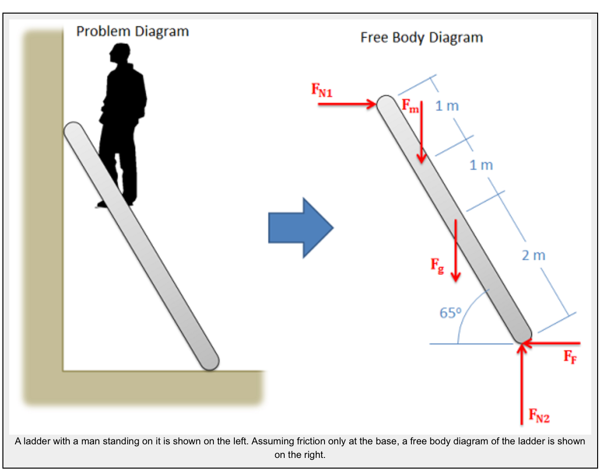
How to Construct a Free-Body Diagram
There is a systematic, five-step process for drawing a correct FBD. Getting this right is crucial, as any mistake here will lead to incorrect calculations later.
This web page from Engineering Statics provides a clear, step-by-step guide to creating an FBD.
Please read the section titled 'Creating Free Body Diagrams.' It lists and explains five key steps, from isolating the object to labeling the diagram.
To summarize the key steps from the reading:
- Select and isolate the object: Draw a simplified outline of the body of interest, separate from all its surroundings and supports.
- Select a reference frame: Draw a coordinate system (e.g., x-y axes) to define positive directions for forces.
- Identify all loads: Add arrows for all applied external forces and moments. This includes gravity (weight), pushes, pulls, and any other specified loads.
- Identify all reactions: This is the most important step. At every point where you detached the body from a support, add the forces and/or moments that the support was exerting on the body. We'll detail these next.
- Label the diagram: Add values or variable names to all forces, moments, dimensions, and angles.
Identifying Support Reactions
The trickiest part of drawing an FBD is correctly replacing supports with the forces they generate. A support's purpose is to prevent motion (translation) or rotation. Each type of motion it prevents corresponds to a reaction force or reaction moment.
For 2D problems, the most common supports are:
- Cables, Ropes, or Wires: Can only pull (create tension). The reaction is a single force acting along the direction of the cable.
- Rollers or Smooth Surfaces: Prevent translation perpendicular to the surface. The reaction is a single force normal (perpendicular) to the surface. The object is free to move parallel to the surface and to rotate.
- Pins or Hinges: Prevent translation in both x and y directions. The reaction is two separate force components (e.g., and ). The object is still free to rotate about the pin.
- Fixed Supports (e.g., a beam embedded in a wall): Prevents all motion. The reaction consists of two force components ( and ) AND a reaction moment ().
The following video provides a clear, visual summary of these common 2D support reactions.
Equilibrium of Rigid Bodies (2D - Coplanar Forces) | Mechanics Statics | (Solved examples)
This video from Question Solutions clearly illustrates the forces and moments associated with different types of supports.
Please watch from 01:04 to 02:57. Pay close attention to how a roller, a pin, and a fixed support are represented on an FBD.
Test your understanding!
Imagine a simple footbridge represented as a beam. It is supported by a pin on the left end (A) and a roller on the right end (B). What are the unknown reactions you would draw on the FBD of the beam?
Show answer
- At the pin support (A), you would draw two unknown force components: a horizontal force and a vertical force .
- At the roller support (B), you would draw one unknown vertical force , acting perpendicular to the bridge.
Example of Creating an FBD
Now let's see these steps applied to a complete problem. The video below works through an example of a beam with a distributed load, a pin, and a roller. Don't worry about the calculations for now; just focus on how the FBD is constructed.
Equilibrium of Rigid Bodies (2D - Coplanar Forces) | Mechanics Statics | (Solved examples)
Watch this segment to see how to draw the FBD for a beam with a pin, a roller, and an applied load.
Watch from 05:29 to 06:10. Observe how the pin at B is replaced with two forces (Bx, By) and the roller at A is replaced with one force (Ay). Also, note how the distributed load (the rectangle of arrows) is simplified into a single resultant force.
This process of isolating a body and representing all interactions as forces and moments is the key to turning a complex physical system into a model that we can analyze with the equations of equilibrium, which we will cover in upcoming lessons.
Conclusion
In this lesson, we introduced the concept of the Free-Body Diagram as the foundational tool for statics. You are now equipped to tackle the first and most critical step in analyzing rigid bodies.
Key Takeaways:
- A Free-Body Diagram (FBD) is a sketch of an object isolated from its surroundings, showing all external forces and moments acting on it.
- To create an FBD, you must isolate the body, add all applied loads (like gravity), and replace all supports with their corresponding reaction forces and moments.
- The type of support determines the reactions:
- Roller/Smooth Surface: 1 force (normal to surface)
- Pin/Hinge: 2 force components
- Fixed Support: 2 force components and 1 moment
- A complete FBD must be fully labeled with all forces, moments, dimensions, and a coordinate system.
Next Lesson Preview:
Now that we know how to draw all the forces on a body, the next step is to work with these forces mathematically. In the next lesson, we will cover how to resolve forces into components and calculate resultant forces and moments using vector methods. This will give us the tools we need to start building the equations of equilibrium.
Can't find a good explanation? Sign up and we'll make it for you
Sign up