
In our previous lesson, we focused on the conceptual groundwork for modeling object lifecycles. You learned how to analyze a system's behavior and derive its essential components: states, events, transitions, guards, and actions. Now, we will bridge the gap from concept to creation. This lesson will equip you with the practical skills to write Mermaid code for state diagrams, turning your analytical models into clear, renderable visuals.
Our primary goal is to master the Mermaid syntax for creating state diagrams that include all the key features we've discussed. We will cover how to define initial and terminal states, how to encode transitions with guards and actions, and how to organize complex behavior using composite states. By the end of this session, you'll be able to construct sophisticated state machine diagrams from scratch.
From Concepts to Code: Basic Syntax
Let's begin with the fundamental syntax for building a state diagram in Mermaid. The core elements are states and the transitions that connect them. The Mermaid documentation provides a clear and concise reference for these basics.
Please read the following sections from the Mermaid documentation. They will introduce you to the syntax for defining states, creating transitions between them, and marking the initial and final states of the machine.
Start by reviewing the initial sections of the document.
First, focus on the section defining states. This shows the different ways you can declare a state, from a simple ID to a more descriptive label. Next, read about transitions. Pay close attention to the --> arrow syntax and how to add a descriptive label to a transition. Finally, review the short section on Start and End states. The [*] syntax is the standard way to denote the entry and exit points of the state machine.
To summarize the key syntax:
- Diagram Type: Every state diagram must begin with
stateDiagram-v2. - States: You can declare a state simply by using it in a transition (e.g.,
A --> B), or more explicitly with a description:state "In Progress" as InProgress. - Transitions: An arrow
-->creates a transition. Text is added after a colon:A --> B : An event occurred. - Initial/Terminal States: A transition from
[*]defines the start state ([*] --> A). A transition to[*]defines a terminal state (B --> [*]).
Here is a simple example combining these elements:
This diagram shows a system that starts in Idle, moves to Processing when data is received, and can either return to Idle or move to a terminal Error state.
Encoding Guards and Actions
In the previous lesson, we established the standard UML transition label format: trigger-event [guard-condition] / action. While Mermaid doesn't have a separate syntax for each of these three components, it fully supports this convention through the single transition label. You simply write them all as part of the text string.
This convention is described clearly in the draw.io documentation on UML state diagrams.
UML state machine diagram - Draw.io
Please locate the "Transitions" section in this document.
Read the short paragraph under the "Transitions" heading, focusing on the standard format for a transition label. This reinforces the trigger [guard] /action structure.
To put this into practice, let's translate the "Document Approval Workflow" example from our last lesson into a complete Mermaid diagram.
Recap of the workflow:
A new document starts in the 'Draft' state. The author can update the document. When ready, the author submits it for review, moving it to 'Awaiting Review' and notifying the review team. A manager can assign it, moving it to 'In Review'. A reviewer can approve it, moving it to 'Approved', or reject it, sending it back to 'Draft' with comments.
Here is the Mermaid code for that workflow, applying the trigger [guard] / action convention:
In this diagram:
submit / notifyTeam()is a transition with a trigger (submit) and an action (notifyTeam()).reject [with comments] / addComments()includes a trigger (reject), a guard ([with comments]), and an action (addComments()).
Managing Complexity with Composite States
As state machines grow, they can become cluttered. A powerful way to manage this complexity is by using composite states—states that contain their own nested sub-states. This is analogous to how you might structure a complex software component into smaller, more manageable modules. An outer state can represent a major phase of an object's life, while the inner states model the detailed behavior within that phase.
This diagram of an RPG character's lifecycle provides a great visual example. The intro, combat, and defeated states are high-level phases, each with its own internal sequence of sub-states.

Mermaid uses curly braces {} to define composite states. You can nest them to create a hierarchy of states.
Please navigate to the "Composite states" section in the Mermaid documentation.
Read the syntax description and review the code examples. Note how the state keyword and curly braces {} are used to enclose the sub-states. Also, notice the important rule mentioned at the end about transitions between states in different composites.
The key syntax is state "Outer State" as Outer { ... }, where the sub-state machine is defined inside the braces. You can define transitions into or out of the composite state, as well as transitions between its internal sub-states.
A Complete Example: Access Control System
Now let's analyze a complete, practical example that combines all the concepts: initial/terminal states, guarded transitions, and composite states. The following diagram models the behavior of an RFID access control system.
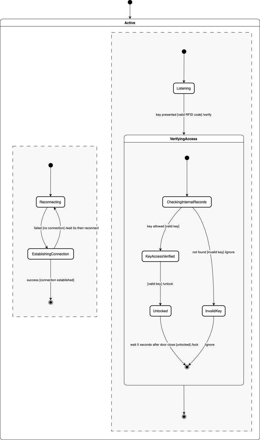
This diagram looks complex, but it's built from the same elements we've been learning. The Active state is a large composite state that contains the system's main operational logic. Inside it, VerifyingAccess is another composite state, handling the details of key validation.
Now, let's examine the Mermaid code that generates this exact diagram.
UML state machine diagram - Draw.io
In the same draw.io document, scroll down to the section "Create a UML state diagram from text".
Carefully study the large Mermaid code block. Don't worry about the Reconnecting part for now (it demonstrates concurrency, which is a more advanced topic). Focus on the Listening and VerifyingAccess logic. Try to map the syntax back to the visual diagram.
Let's break down the key parts of that code:
- Top-Level States: The system starts
[*]and immediately enters theActivecomposite state.
- A Guarded Transition with an Action: The transition from
ListeningtoVerifyingAccessis a perfect example of ourtrigger [guard] / actionformat.
-   **Trigger**: `key presented`
-   **Guard**: `[valid RFID code]`
-   **Action**: `/verify`
3. A Nested Composite State: The VerifyingAccess state contains its own internal logic for checking the key. Notice it has its own initial [*] state.
This demonstrates how composite states encapsulate a sub-problem. The `InvalidKey` state transitions to the composite's *own* terminal state `[*]`, which then causes the `VerifyingAccess` state itself to complete.
By studying this example, you can see how these few syntactic rules can be combined to model sophisticated, real-world system behavior.
Conclusion
In this lesson, you have translated the theoretical components of state machines into concrete Mermaid syntax. You are now equipped to create your own state diagrams to model the lifecycle of any object or system.
The key takeaways are:
- Basic Syntax: Diagrams start with
stateDiagram-v2and use-->for transitions and[*]for initial/terminal states. - Guarded Transitions: The convention
trigger [guard] / actionis expressed as a simple text label on a transition. - Composite States: The
state "Name" as ID { ... }syntax allows you to nest state machines, which is essential for managing complexity and creating hierarchical models.
You have now completed our module on modeling dynamic behavior. You've explored use cases, activities, and state lifecycles. In our next module, we will shift our focus from behavior to structure, starting with a lesson on how to construct a UML component diagram to show how a system is organized into subsystems and dependencies.
Can't find a good explanation? Sign up and we'll make it for you
Sign up