
Welcome to this lesson on modeling object lifecycles. We will be exploring UML State Machine Diagrams, a powerful tool for visualizing how an object or system behaves over time. Your background in electronics and software development means you're already familiar with systems that exist in different states; this lesson will provide the formal UML framework to describe and analyze such behavior precisely.
Our goal today is to learn how to dissect a narrative description of an entity's lifecycle and extract the fundamental components needed to model it: states, events, transitions, guards, and actions. This process of derivation is the crucial first step before you can create any diagram. By the end of this lesson, you'll be able to look at a system's behavior and see the underlying state machine structure.
The Anatomy of a Lifecycle
At its core, a state machine diagram models the lifecycle of a single object or component. It answers the question: "What are the possible conditions this object can be in, and what causes it to move between those conditions?"
To build these diagrams, we first need a clear vocabulary. The following five concepts are the essential building blocks.
- State: A condition or situation in the life of an object, during which it satisfies some condition, performs some activity, or waits for some event. An object remains in a state for a finite amount of time. Examples:
Idle,In Progress,Completed. - Event: An occurrence that can trigger a state transition. Events can be signals, calls, the passage of time, or a change in conditions. Examples:
user clicks save,payment received,timer expires. - Transition: A relationship between two states indicating that an object in the first state will perform certain actions and enter the second state when a specified event occurs and specified conditions are satisfied. It's the arrow connecting two states.
- Action: An executable, atomic computation. Actions can be executed upon entry to a state, on exit from a state, or as part of a transition. Examples:
updateDatabase(),sendEmail(),startAlarm. - Guard: A boolean condition that must be true for a transition to be triggered. It provides a way to add conditional logic to your state machine. A transition only "fires" if its guard condition evaluates to true. Example:
[balance > 0],[isUserAdmin == true].
To see how these concepts are defined more formally, please read the "Basic State Machine Concepts" section of the following document. It provides excellent, detailed explanations of each element.
A Crash Course in UML State Machines
This document by Miro Samek offers a thorough and technically precise introduction to state machines. We'll focus on the section that defines the core concepts you'll be using.
Please read from the beginning of Section 1.2 up to the end of the Run-to-Completion section. Pay close attention to the distinctions made between states and variables, and the specific definitions of guards, events, and actions.
The syntax for labeling a transition is crucial as it packs a lot of information onto a single arrow. The standard format is:
trigger-event [guard-condition] / action
Derek Banas provides a very clear, concise explanation of this format. Watching this short segment will help solidify your understanding of how these three elements work together on a transition.
This video from Derek Banas's popular UML series breaks down the components of a complex transition.
Watch the section from where he explains the trigger, guard statement, and transitional behavior on a single transition arrow. This visual breakdown is extremely helpful.
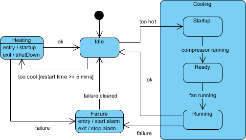
Let's look at an example diagram to see all these parts in context.
Deriving a State Machine from a Description
Now we move to the central task of this lesson: taking a problem description and deriving these components. This is a process of analysis and abstraction, moving from prose to a formal structure.
Let's walk through this process with a simple example: a document approval workflow.
A new document starts in the 'Draft' state. The author can update the document as many times as they need. When ready, the author can submit it for review, which moves it to the 'Awaiting Review' state and notifies the review team. A manager can then assign the document to a specific reviewer, moving it to the 'In Review' state. The reviewer can either approve the document, moving it to 'Approved', or reject it, sending it back to 'Draft' with comments. An approved document cannot be edited further.
Let's break this down systematically.
Step 1: Identify the States
Look for the nouns that describe the status or condition of the document. What are the distinct phases of its life?
DraftAwaiting ReviewIn ReviewApproved
Step 2: Identify the Events and Transitions
Look for the verbs or actions that cause the document to change from one state to another.
- From
DrafttoAwaiting Review: The event is "author submits for review". - From
Awaiting ReviewtoIn Review: The event is "manager assigns reviewer". - From
In ReviewtoApproved: The event is "reviewer approves". - From
In ReviewtoDraft: The event is "reviewer rejects".
We also have an implicit transition:
- From
DrafttoDraft: The event is "author updates document". This is a self-transition.
Step 3: Identify Actions and Guards
Look for the specific computations or side effects that happen, and the rules that govern transitions.
- Actions:
- When transitioning from
DrafttoAwaiting Review:/ notify review team. - When transitioning from
In Reviewback toDraft:/ add reviewer comments.
- When transitioning from
- Guards:
- The description implies that only an author can submit. While we might model this with actor permissions, in a state machine, we could represent it as a guard on the submission transition:
[user is author]. - The rule "An approved document cannot be edited further" means there are no outgoing transitions from the
Approvedstate that allow for editing.
- The description implies that only an author can submit. While we might model this with actor permissions, in a state machine, we could represent it as a guard on the submission transition:
By following these steps, we've systematically translated the narrative into the formal components of a state machine, which we could then diagram.
This systematic approach is key. To see it applied to a more complex, real-world software problem, you will now read a walkthrough of designing a state machine for a calculator. This example does an excellent job of showing how design decisions are made and how an initial simple model is refined to handle more complexity.
A Crash Course in UML State Machines
This part of the "Crash Course" document applies the principles we've just discussed to a concrete design problem. It demonstrates the iterative process of deriving and refining states and transitions.
Please read Part 3 of the document, starting from the problem specification for the calculator, through the "High-Level Design" and subsequent refinement sections, up to the end, before the final diagram. Focus not just on the final result, but on the reasoning used to identify the initial states, factor out common behavior into superstates, and handle tricky logic like the dual-use minus sign.
Conclusion
In this lesson, we established the vocabulary for describing object lifecycles within the UML framework. You learned to identify the five key elements: states, events, transitions, guards, and actions. Most importantly, you practiced a systematic process for deriving these elements directly from a narrative or problem description, moving from informal requirements to a structured model.
The key takeaways are:
- State machine diagrams model the behavior of a single entity over time.
- Every component—state, event, transition, guard, and action—has a precise meaning and role.
- The derivation process involves identifying states (stable conditions), events (triggers), transitions (pathways), guards (rules), and actions (work).
This analytical skill is the foundation for everything that follows. In our next lesson, we will put this knowledge into practice by learning the Mermaid syntax to encode these components. You'll take the conceptual models you've learned to derive today and turn them into shareable, renderable diagrams, including more advanced constructs like composite states.
Can't find a good explanation? Sign up and we'll make it for you
Sign up