
Hello! Welcome to our first lesson on AC circuits.
In the previous module, we concluded our journey through electromagnetic theory by seeing how the dynamic interplay of electric and magnetic fields gives rise to self-propagating electromagnetic waves. These waves, which include everything from radio to light to X-rays, are fundamentally sinusoidal oscillations. Now, we'll bring this concept of oscillation from the vastness of space right into the circuits that power our world.
Today's learning outcome is to describe alternating current and voltage using sinusoidal functions, distinguishing between peak and RMS values. This is the foundational language of AC circuits. To analyze mains power or generators, we must first have a clear and quantitative way to describe the alternating voltages and currents they produce.
From DC to AC: The Language of Oscillation
You'll recall from your previous studies that Direct Current (DC) is straightforward: it has a constant magnitude and flows in one direction. Alternating Current (AC), however, periodically reverses its direction and continuously changes its magnitude.
The most fundamental and common form of AC is the sinusoidal waveform. As you know from your work in mathematics and physics, sinusoids (sines and cosines) are the natural language of simple harmonic motion and wave phenomena. This is no accident; as we'll see in a later lesson, the voltage produced by a rotating generator is naturally sinusoidal.
AC Waveform and AC Circuit Theory
Let's start by formally defining the AC waveform and its basic characteristics. This article from Electronics Tutorials provides a clear contrast between DC and AC and introduces the key terminology.
Please read the first two main sections: 'What is an AC Waveform?' and 'AC Waveform Characteristics'. Focus on the definitions of Period (T), Frequency (ƒ), and Amplitude (A), and the relationship ƒ = 1/T.
The Mathematical Description of an AC Voltage
To work with these waveforms, we need a precise mathematical expression. A general sinusoidal voltage (or current) can be described as a function of time, .
02 - Sinusoidal AC Voltage Sources in Circuits, Part 1
This video from Math and Science gives a great breakdown of the standard equation for a sinusoidal AC source. It also provides a valuable explanation for why we use angular frequency.
Please watch from 07:06 to 10:30, and then from 12:57 to 17:40. The first segment introduces the general form of the AC voltage equation and its components. The second segment explains the relationship between period (T), frequency (f), and angular frequency (ω). Pay close attention to the justification for using ω (radians per second) inside the trigonometric function.
As the video explained, the general form is:
Let's consolidate the key components:
- Amplitude (): This is the peak value or maximum value the voltage reaches in a cycle. The waveform oscillates between and . The peak-to-peak voltage is simply .
- Angular Frequency (): Measured in radians per second. It's related to the conventional frequency (in Hertz, Hz) by the crucial formula . As highlighted in the video, we use so that the argument of the cosine function, , is an angle in radians, which is mathematically required.
- Phase Angle (): This value, in radians, determines the horizontal shift of the waveform. It tells us the voltage at . A phase angle of zero means the wave starts at its peak (for a cosine function), while a phase angle of would make it a sine function. We will explore the significance of phase angle in great detail in the next lessons, as it becomes critical when comparing the voltage and current in a circuit.
Quantifying AC: Peak, Average, and RMS
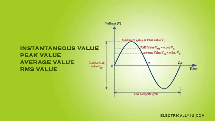
A key challenge with AC is that its value is always changing. If someone says a wall outlet provides "230 volts," what does that number actually mean? Is it the peak? The average? Something else? To answer this, we need to define three key ways to quantify an AC signal.
-
Peak Value (): We've already defined this. It's the absolute maximum value the waveform reaches. While simple to identify, it doesn't fully capture the waveform's capacity to do work.
-
Average Value (): If you average a sinusoidal waveform over one full cycle, the result is zero, as the positive and negative halves cancel perfectly. Therefore, the "average value" in AC terminology refers to the average over a half-cycle. For a sinusoid, this can be calculated via integration:
This value is used in some specific applications, like designing certain types of power supplies, but it's not the most common measure. -
RMS (Root Mean Square) Value (): This is the most important and widely used measure for AC voltage and current.
The RMS value is the effective value of an AC source that delivers the same average power to a resistor as an equivalent DC source.
For example, a 120V (RMS) AC source will light a resistive bulb to the same brightness as a 120V DC battery. This is why it's sometimes called the "effective value." The name "Root Mean Square" describes its mathematical origin: you take the function, Square it, find the Mean (average) of the squared function, and then take the square Root of that mean.
For a sinusoidal waveform, this process yields a simple relationship with the peak value:
The sine wave explained (AC Waveform analysis)
The following video explains the concept of RMS value using the practical 'equivalent heating effect' analogy and shows how to calculate it from the peak value.
Please watch from 07:07 to 09:43. Focus on the definition of RMS as the AC value that gives the same heating effect as the equivalent DC voltage. Note the simple conversion factor of 0.707.
Crucially, when you see a voltage rating for an AC appliance or a mains power outlet (e.g., 230V in the UK, 120V in the US), it is always the RMS value unless explicitly stated otherwise.
Test your understanding!
A standard UK mains socket provides 230V at a frequency of 50Hz.
- Is the 230V value the peak, average, or RMS voltage?
- What is the peak voltage () of the mains supply?
- What is the full mathematical expression for the voltage as a function of time, ? (Assume a sine function, which corresponds to in a convention).
Show answer
- The 230V value is the RMS voltage. Standard AC voltage ratings are always given in RMS.
- We know . Therefore, the peak voltage is .
So, the voltage at the socket actually swings between +325V and -325V every cycle! - First, we need the angular frequency .
Now, we assemble the equation :
This example is taken directly from one of your resources, LINK (Module 2 A.C. Circuits), which uses a cosine function but arrives at the same physical values.
Summary and Conversion
To make these conversions easier, you can use a simple table. The following resource provides definitions for RMS and Average values and concludes with a very handy conversion chart.
AC Waveform and AC Circuit Theory
This page summarizes the definitions of Average and RMS values and provides a useful conversion table.
Quickly read the sections 'The Average Value of an AC Waveform' and 'The RMS Value of an AC Waveform' to reinforce the concepts. Then, pay close attention to the 'Sinusoidal Waveform Conversion Table' at the end. It's a useful reference for quickly converting between peak, RMS, and average values.
Conclusion
In this lesson, we have established the fundamental language for describing alternating currents and voltages.
Key Takeaways:
- AC voltage and current are most commonly represented by sinusoidal functions of time: .
- This description is defined by its amplitude (), angular frequency (), and phase ().
- The Peak Value () is the maximum instantaneous value.
- The RMS (Root Mean Square) Value is the "effective" value, representing the equivalent DC value for power delivery ().
- Standard AC voltage ratings for mains power and equipment are given in RMS.
Preview of the Next Lesson:
Now that we can describe an AC voltage source, the next logical question is: what happens when we connect it to a circuit? In the next lesson, we will explore the fundamental behavior of resistors, capacitors, and inductors in AC circuits. We will discover that while resistors behave similarly to how they do in DC, capacitors and inductors introduce a fascinating new element: a phase shift between the voltage across them and the current through them.
Can't find a good explanation? Sign up and we'll make it for you
Sign up