
Hello! Welcome to your sixth lesson on electricity.
In our last lesson, we distinguished between real, reactive, and apparent power, and defined the power factor (PF) as the ratio of real to apparent power, . We saw it's a measure of how effectively the supplied power is being used to do useful work.
Today, we'll explore the profound practical consequences of this ratio. We will address the learning outcome: Explain the concept of power factor and its impact on power generation and transmission efficiency. You'll discover why a seemingly abstract number has significant economic and engineering implications for our power grids, directly connecting to your goal of understanding mains power and generators on a practical level.
The Problem with "Useless" Power
Let's start with a simple analogy to build your intuition. In the last lesson, we saw that reactive power () doesn't perform useful work; it's just energy sloshing back and forth between the source and the load's magnetic or electric fields. You might think that if it does no work, we can just ignore it. However, it has very real consequences.
To understand why, let's watch a short segment from a video that introduces a famous analogy.
Power Factor Explained - The basics what is power factor pf
This video from The Engineering Mindset uses the 'beer analogy' to provide an excellent intuitive framework for understanding the different types of power and the meaning of power factor.
Please watch the first two minutes of the video (00:04 - 02:03). Focus on the analogy: the beer is the useful 'real power' (kW), the foam is the 'reactive power' (kVAr), and the whole glass is the 'apparent power' (kVA) you pay for.
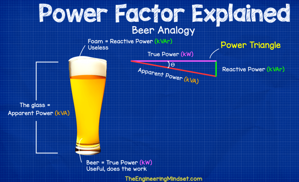
The key insight from this analogy is that even though the foam (reactive power) isn't what you want, it still takes up space in the glass (apparent power). The power grid works the same way. The network of wires, transformers, and generators must be large enough to handle the entire "glass" (the apparent power, ), even if the customer is only using the "beer" (the real power, ).
The Core Issue: Low Power Factor Means Higher Current
Let's translate this into electrical terms. Remember the formulas from last lesson:
If we rearrange the first equation for current, we get:
Here, is the real power required by a load (e.g., the mechanical output of a motor), and is the supply voltage, which is kept relatively constant (e.g., 230V or 415V in the UK). Notice what this equation implies about the power factor, :
For a given amount of real power (P), a lower power factor requires a higher current ().
This is the central problem of poor power factor. The electrical system has to supply this larger current, and that has major consequences.
Let's see a practical example of this.
Power Factor Explained - The basics what is power factor pf
The same video provides a clear, quantitative comparison between two motors doing the same amount of work but with different power factors.
Watch the segment from 04:43 to 06:16. Notice how the motor with the lower power factor needs to draw more apparent power (kVA) and therefore more current to produce the same 10 kW of real power.
Impact on Power Generation and Transmission
So, what's wrong with higher current? It creates a cascade of inefficient and costly effects throughout the power grid.
-
Increased Power Losses: Power lines have resistance, . The energy lost as heat during transmission is given by . Because the losses are proportional to the square of the current, even a modest increase in current due to poor power factor can cause a significant increase in wasted energy. This is energy that the power station has to generate (and burn fuel for) but that never reaches the consumer to do useful work.
-
Increased Equipment Size and Cost: Every component in the grid—from the generator at the power station to the transformers and the wiring—must be rated to handle the total apparent power (, in VA) and the total current (, in Amps), not just the real power (, in W). A low power factor means all this equipment must be larger and more expensive to deliver the same amount of useful power.
-
Reduced System Capacity and Voltage Drops: The higher currents take up capacity on the transmission lines. A line might be physically capable of carrying more real power, but it's "full" because of the excessive current drawn by loads with poor power factor. Furthermore, this higher current causes a larger voltage drop () across the transmission lines, which can degrade the quality of power supplied to end-users.
Because of these effects, which increase their operating and capital costs, utility companies often impose financial penalties on large industrial and commercial customers with low power factors. Given your background in economics, you can appreciate this as a classic Pigouvian tax—a charge designed to discourage an activity that creates negative external costs for the system.
The following document from ABB provides an excellent quantitative summary of these effects.
This technical note from ABB quantifies the real-world impact of power factor on equipment sizing and cost. It's a great example of applying these electrical principles in an industrial context.
Please read the section 'Why is good power factor important?' and pay close attention to Table 1: Effects of power factor. This table shows concretely how improving the power factor for a 75 kW load reduces the required current, which in turn allows for smaller transformers and thinner wires. Also, glance at Table 2 to see an example of how a utility company might apply cost multipliers based on power factor.
The Solution: Power Factor Correction (PFC)
Since the problem is caused by reactive power, the solution is to manage it locally. Most large industrial loads are inductive (e.g., motors), which consume reactive power and cause a lagging power factor. We can counteract this by connecting capacitors, which supply reactive power, in parallel with the load.
When a correctly sized capacitor is placed at the load, it provides the reactive power the motor needs. The motor and capacitor simply exchange reactive power between themselves. The power source no longer has to supply this reactive power; it only needs to provide the real power. As a result, the total current flowing from the source through the transmission lines is significantly reduced, which in turn reduces losses and frees up system capacity.
The following video provides a detailed, step-by-step analysis of this process. It is quite in-depth, but with your mathematical background, you should be able to follow the logic clearly. It perfectly demonstrates how PFC increases the efficiency of the overall system (generator + transmission lines + load).
Power Factor and Efficiency in AC Circuits (Full Lecture)
In this final video, Jim Pytel walks through a comprehensive example comparing a system before and after power factor correction. This will tie everything together.
This is a longer segment (28:07 - 43:09), so feel free to pause as needed. The setup involves a source, a transmission line (modeled as a resistor), and a load. First, he analyzes the system without correction, calculating the current in the transmission line and the resulting power loss. He finds the overall system efficiency. Then, he adds a capacitor in parallel with the load (inside the 'room'). He re-calculates the total source current, showing that it has decreased. Finally, he calculates the new, lower power loss in the transmission line and the new, higher overall system efficiency. Focus on the big picture: how adding the capacitor reduces the current from the source and, consequently, the transmission losses.
Test your understanding!
A factory has a large motor that draws 100 kW of real power from a 415 V supply. Due to its inductive nature, it has a poor power factor of 0.75 lagging.
- Calculate the apparent power (S) the factory draws from the grid.
- Calculate the current () flowing from the grid to the factory.
- The factory installs a capacitor bank to improve the power factor to 0.95 lagging, while the motor still performs the same 100 kW of work. Calculate the new apparent power and the new current drawn from the grid.
- By what percentage did the current drawn from the grid decrease? What does this imply for the losses in the supply cables?
Show answer
-
Initial State (PF = 0.75):
- Apparent Power (S):
- Current (I): Since (for three-phase, it's , but we can work with single-phase logic for comparison or just use ):
(Note: The exact formula depends on whether 415V is line-to-line, but for comparing the change in current, this direct proportionality is what matters).
-
Corrected State (PF = 0.95):
- The real power is still 100 kW.
- New Apparent Power ():
- New Current ():
-
Percentage Decrease in Current:
- Decrease =
- The current drawn from the grid decreased by over 21%!
- Since transmission losses are proportional to , the new losses will be of the original losses. This represents a reduction in transmission losses of about 38%.
Conclusion
We've established that power factor is not just an academic detail but a critical parameter with tangible economic and physical impacts on power systems.
Key Takeaways:
- A low power factor means that for a given amount of useful work (real power, kW), a higher total current must be drawn from the grid.
- This higher current leads to greater energy losses in transmission lines, requiring more fuel to be burned at the power station for the same customer output.
- It also necessitates larger, more expensive equipment (generators, transformers, cables) throughout the grid, as they must be sized for the apparent power (kVA), not just the real power.
- Utilities penalize large consumers for low power factor to recoup these costs and incentivize efficiency.
- Power Factor Correction (PFC), typically by adding capacitors to offset inductive loads, reduces the current drawn from the source, thereby cutting transmission losses and increasing the overall efficiency of the power system.
Preview of the Next Lesson:
This concludes our deep dive into AC power. We now have a solid understanding of voltage, current, impedance, and the various facets of power. In the next module, we will shift our focus to where this electricity comes from. We will begin by exploring the fundamental principles of electrical generators, addressing the learning outcome: Explain how rotating a coil in a magnetic field produces a sinusoidal AC voltage via Faraday's law. This will connect the concepts of electromagnetism directly to the AC voltage and power we've just studied.
Can't find a good explanation? Sign up and we'll make it for you
Sign up