
Welcome back. Last time, you learned to classify controls by how they are implemented and what they do. That matters here because an architecture diagram gives those controls a location: a firewall rule sits at a network boundary; authorization operates at an API entry point; logging observes data flows; backups protect a data store.
In this lesson, you will turn a simple backend architecture into a security-relevant data flow diagram (DFD). You will identify what needs protection, where data enters, where it travels, and—most importantly—where the system’s trust assumptions change. This is the foundation for later threat modeling, risk assessment, and secure design reviews.
From a system sketch to a security model
An ordinary architecture diagram may show services, databases, and queues. A security-oriented diagram must answer a more focused question:
Where can untrusted data or actors interact with valuable parts of the system?
A DFD is useful because it represents a system in terms of:
- External entities — people, services, or systems outside the scope you control.
- Processes — components that receive, transform, validate, or act on data.
- Data stores — places where data persists.
- Data flows — directed movement of meaningful data between components.
- Trust boundaries — places where trust, privilege, ownership, or security assumptions change.
The goal is not a perfect deployment diagram. It is a model that is accurate enough to support security decisions.
For a backend service, a useful first-pass DFD usually has the detail of a level-one diagram: enough to show the client, public-facing service, application logic, databases, and important external integrations, without expanding every controller method or database table.
STRIDE Threat Modeling for Beginners - In 20 Minutes
Watch “STRIDE Threat Modeling for Beginners – In 20 Minutes” from Netsec Explained for a compact visual introduction to DFD levels and trust-boundary placement. The video uses simple web-application examples that map well to a backend-service architecture.
Watch DFD levels to see the difference between a quick context diagram and a more useful level-one view. Then watch trust boundaries, focusing on the reasoning for drawing a boundary between a user and an application, and between the application and its database.
A key practical principle follows from this: a diagram has enough detail when you can point to each important interaction and explain the security assumptions that make it safe.
The four things you must mark
Assets: what is worth protecting
An asset is anything whose confidentiality, integrity, or availability matters to the organization. It is not limited to a physical server or a database.
For a typical order-management backend, meaningful assets might include:
| Asset ID | Asset | Why it matters | Likely location |
|---|---|---|---|
| A1 | Customer profile and order data | Contains personal and business data | PostgreSQL database |
| A2 | Login sessions or access tokens | Can be used to act as a user | Browser-to-API flow; application memory |
| A3 | Administrative capability | Allows refunds, account changes, or configuration changes | Admin API and identity system |
| A4 | Database credentials or service secrets | Could enable direct access to protected systems | Secret store or application runtime |
| A5 | Order-service availability | Service interruption affects customers and operations | API, database, dependent services |
| A6 | Audit logs | Support detection and investigation | Logging service or log store |
Notice that assets can be:
- Data, such as personal data, passwords, secrets, logs, or exports.
- Capabilities, such as the ability to issue refunds or execute privileged database queries.
- Services, such as the availability and integrity of an API.
- Trust relationships, such as a valid identity-provider assertion or a service account’s permissions.
On a small DFD, you do not need a separate shape for every asset. Instead, label a data store or flow with concise asset tags such as A1: customer and order data. Keep a small asset list beside the diagram when more explanation is needed.
Data flows: what moves, in which direction
A data flow is a directed arrow showing meaningful data moving between two components. Every arrow should answer:
- Who sends it?
- Who receives it?
- What data is moving?
- What protocol or interface carries it, when relevant?
Avoid arrows labelled only “data” whenever you can be more precise. Compare:
- Weak:
API -> Database: data - Better:
Order API -> PostgreSQL: order lookup and update queries - Better still:
Order API -> PostgreSQL: parameterized order queries over TLS
You do not need to document every HTTP header on a high-level diagram. But you should identify data whose exposure or modification would matter:
- credentials, passwords, and MFA codes;
- session cookies, bearer tokens, or API keys;
- user input such as search terms, order IDs, file uploads, and webhook payloads;
- personal information and payment-related records;
- admin commands;
- audit events;
- database queries and results.
Request and response are often best shown as separate arrows because they carry different data. A request may carry user input and an access token; the response may carry account records, errors, or a downloadable report.
Entry points: where the system accepts interaction or input
An entry point is an interface through which an actor can interact with the system or provide it with data. An attacker needs an entry point to influence a system, so these locations deserve deliberate attention.
For a backend service, entry points often include:
- a public HTTPS endpoint, such as
POST /api/orders; - a login endpoint;
- an administrative portal or administrative API;
- a payment-provider webhook endpoint;
- a file-upload endpoint;
- an SSH or VPN administration interface;
- an internal message-queue consumer;
- a CI/CD deployment interface.
A single user action can cross several layered entry points. For example, a user’s request to POST /api/orders reaches:
- the public HTTPS listener;
- the reverse proxy or API gateway;
- the route handler;
- the application’s request parser;
- the authorization logic;
- possibly a database query interface.
For a level-one DFD, mark the important external interface, such as EP-1: public HTTPS API, and record deeper layers in notes if they are material to the analysis.
An outbound call is not automatically an entry point into your system. However, if an external provider later sends a webhook or callback, that inbound callback is an entry point. Likewise, data received in the response to an outbound API call should still be treated as untrusted input.
Trust boundaries: where assumptions change
A trust boundary is a line across which data moves from one trust level, privilege level, ownership domain, or security zone to another.
A boundary is not simply “anything connected by a network.” It marks a place where you must reconsider assumptions about the actor, data, identity, or component on the other side.
Common backend trust boundaries include:
- the public internet crossing into your public API;
- an authenticated user becoming a privileged administrator;
- a reverse proxy passing a request to an application service;
- an application service connecting to a database;
- your environment calling a third-party payment or email provider;
- a CI/CD platform deploying into production;
- a containerized application calling the host, cloud metadata service, or control plane.
The boundary between an application and database remains important even if both run in the same virtual private network—or even on the same host. The application process and database typically use different identities and privileges. A compromise of the web-facing application should not automatically become unrestricted database access.
Read OWASP’s “Threat Modeling Process” for a concise, practical definition of entry points, assets, and DFD elements. Its college-library example is deliberately simple, which makes the modeling conventions easier to see before applying them to modern APIs.
In the “Entry Points” section, read the entry-point definition and inspect the sample table’s use of identifiers and trust levels. In “Assets,” read the asset discussion, then scan the example asset list for data, services, and capabilities. Finally, in “Data Flow Diagrams,” read the DFD rationale and the symbol table. Focus on the meaning of the symbols rather than reproducing their exact visual style.
Reading a marked-up DFD
The following OWASP college-library DFD shows the core elements together.
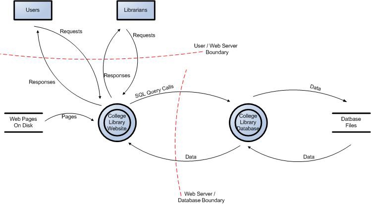
Read the diagram from left to right:
- Users and Librarians are external entities. They are outside the application and should not be assumed trustworthy merely because librarians have more privileges.
- The College Library Website receives requests and returns responses. It is the public-facing process.
- Web Pages on Disk and Database Files are data stores.
- The College Library Database is a separate process responsible for data access.
- The request and response arrows cross the User / Web Server Boundary. This is where untrusted external input first reaches the application.
- The SQL-query and returned-data arrows cross the Web Server / Database Boundary. This is where the application operates using a database identity and gains access to more sensitive information.
The diagram has deliberately few elements. Its purpose is not to explain every internal feature of the library system. It exposes the high-value paths where data enters, gains access to more privileged components, and reaches persistent storage.
This is exactly the perspective that makes a DFD useful: it lets you say, “This request begins outside our control, crosses into a public-facing service, and then causes a database operation against sensitive records.”
A worked backend example
Consider a simple service called OrderHub:
- Customers use a browser or mobile app.
- An API gateway exposes the public API.
- The Order API validates requests and reads or updates order records.
- PostgreSQL stores customer and order data.
- A payment provider sends payment-status webhooks.
- Support administrators use a separate admin interface.
Start with these components:
| DFD element | OrderHub component |
|---|---|
| External entities | Customer client, support administrator, payment provider |
| Processes | API gateway, Order API, admin interface |
| Data store | PostgreSQL orders database |
| Data flows | HTTPS requests, bearer tokens, order payloads, database queries/results, webhook payloads |
| Boundaries | Internet to public API, application tier to database tier, administrator to admin interface, payment-provider integration |
Now make the security-relevant markings.
1. Mark assets
Add concise tags to the relevant components and flows:
A1: customer profile and order dataat PostgreSQL.A2: access tokens and sessionson customer-to-gateway flows.A3: administrative refund and account-management capabilityat the admin interface.A4: payment-status integrityon the payment-provider webhook flow.A5: order-service availabilityacross the gateway, API, and database.
The customer’s name is an asset, but so is the integrity of a payment-status update. An attacker who cannot read the payment event but can alter it could still create fraudulent orders or incorrect refunds.
2. Label the flows
Use labels that communicate data and direction:
| Flow ID | Direction | Meaningful label |
|---|---|---|
| F1 | Customer client → API gateway | HTTPS request: order ID, access token, user input |
| F2 | API gateway → Customer client | HTTPS response: order details or error |
| F3 | API gateway → Order API | Routed authenticated API request |
| F4 | Order API → PostgreSQL | Order lookup or update query |
| F5 | PostgreSQL → Order API | Customer and order records |
| F6 | Payment provider → API gateway | HTTPS webhook: payment event and signature |
| F7 | Support administrator → Admin interface | Admin login and management request |
A gateway-to-API flow can be internal but still important. It may carry identity headers, request metadata, and user-controlled values. “Internal” does not mean “safe by default.”
3. Mark entry points
Annotate interfaces where data first enters an OrderHub component:
EP-1: Public HTTPS APIfor customer requests.EP-2: Payment webhook endpointfor provider events.EP-3: Admin HTTPS interfacefor support staff.EP-4: Database listeneronly if it is reachable from a separate application component or administration network.
The Order API’s database connection is an important interaction, but in most diagrams it is better represented as a data flow across a trust boundary rather than as an internet-facing entry point.
4. Draw and name boundaries
For this example, use three broad boundaries:
| Boundary | What changes across it | Why it matters |
|---|---|---|
| B1: Public internet → OrderHub public edge | Untrusted external party reaches a controlled service | Requests, tokens, headers, and payloads require careful handling |
| B2: Application tier → database tier | Application identity gains database access | Database permissions, credentials, network rules, and query handling matter |
| B3: Support administrator → admin interface | Higher-privilege user accesses sensitive functions | Strong authentication, authorization, and auditing matter |
The payment provider adds an important nuance. It is a known business partner, but its webhook must still cross B1 as externally supplied input. “Expected sender” is not the same as “automatically trustworthy sender.” The receiving service needs a way to establish that the event is authentic and intended for it.
How to decide whether a boundary belongs on the diagram
Draw a trust boundary when at least one of these conditions changes:
-
Identity or privilege
For example, anonymous user to authenticated user, or standard administrator to production administrator. -
Control or ownership
For example, your AWS account to a SaaS provider, or a developer workstation to a managed CI/CD platform. -
Network exposure
For example, internet to DMZ, application subnet to database subnet, or corporate network to a production segment. -
Process or service identity
For example, a web application’s service account connecting to a database account with different permissions. -
Data sensitivity or handling requirement
For example, an API receiving a public search query and then passing account information into a protected data store.
A boundary does not mean the component inside it is perfectly secure, and it does not mean the component outside it is malicious. It means the crossing deserves explicit security assumptions and controls.
For example:
- At B1, you might expect authentication, input handling, rate limits, and request logging.
- At B2, you might expect separate database credentials, least-privilege roles, restricted network access, and encrypted connections.
- At B3, you might expect stronger authentication, role checks, session protections, and audit trails.
This connects directly to the previous lesson: controls only become meaningful in a design when you can identify which risk at which boundary they address.
A repeatable diagramming workflow
Use this sequence for a simple application or backend service.
1. Set a practical scope
Write one sentence such as:
Scope: the public OrderHub API, its admin interface, order database, and payment webhook integration.
Do not begin by mapping every corporate system. Keep the first model narrow enough to finish and revise.
2. Place the external entities first
Add people and systems outside the scope:
- anonymous customer;
- authenticated customer;
- support administrator;
- payment provider;
- identity provider;
- deployment pipeline, if it can reach production.
Distinguish entities when their privileges differ. “User” and “administrator” should not normally be one generic box.
3. Add processes and data stores
Represent components that process data separately from components that persist it.
For example:
- API gateway: process;
- Order API: process;
- PostgreSQL: data store;
- audit-log platform: data store or external entity, depending on scope.
Do not label a database merely “database” if there are multiple kinds of records. A meaningful name such as “Orders and Customer Records” helps reveal the asset.
4. Add arrows before boundaries
Draw every significant data movement, give it a direction, and label its content. Include administrative and third-party paths—not only the primary user journey.
At this stage, ask: “What information can arrive here, and what information can leave?”
5. Draw boundaries around trust zones
Group components that share a similar trust assumption, then draw a boundary where that assumption changes. Name the zones if that improves clarity:
- Public Internet
- Public Service Edge
- Application Tier
- Data Tier
- Third-Party Provider
- Administration Zone
6. Add asset and entry-point identifiers
Use short labels such as A1, EP-1, F1, and B1. Put their fuller definitions in a companion table. This keeps the diagram readable while allowing findings in a later assessment to reference exact locations.
Quality check before using the diagram
A useful DFD should pass this quick review:
- Scope: It is clear what system and integrations are included.
- Actors: External users, administrators, and third parties are represented separately where their privileges differ.
- Assets: Sensitive data, secrets, privileged capabilities, and critical services are identified.
- Flows: Each important arrow has a direction and a meaningful label.
- Entry points: Every place external or lower-trust input enters the system is marked.
- Boundaries: Trust changes are visible, especially internet-to-service, application-to-database, and administrator-to-privileged-function paths.
- Clarity: The diagram can be understood without needing a verbal walkthrough.
- Accuracy: It reflects the system that actually exists, not only the intended design.
For a portfolio artifact, create one level-one DFD for a backend service you own, have built, or can safely model as a fictional project. Include an asset list and a small table of entry points and boundaries. Save both the diagram and a short assumptions note—for example, whether the database is private, how administrators connect, and whether a third-party webhook is used. Those assumptions are as valuable as the drawing because they make the model reviewable.
Key takeaways
A security-oriented architecture diagram should make four things visible:
- Assets are the valuable data, capabilities, services, and trust relationships that need protection.
- Data flows show what meaningful information moves between components and in which direction.
- Entry points are interfaces through which a party can interact with the system or provide input.
- Trust boundaries mark changes in privilege, identity, ownership, network exposure, or security assumptions.
A DFD is not a decoration for a design document. It is a working map of where security controls must operate and where threats are most likely to matter.
Next, you will use this kind of system understanding to rate risks using defined likelihood and impact criteria.
Can't find a good explanation? Sign up and we'll make it for you
Sign up