
Welcome back. In our previous session, we formalized our design's risk profile by conducting a DFMEA. That process helped us identify the features most critical to the grab handle's function, assembly, and in-service performance. Now, we must translate that knowledge into a precise manufacturing instruction: the 2D engineering drawing.
This lesson concludes our work on the grab handle by focusing on how to produce a complete 2D drawing. Our objective is to define a full datum scheme and apply the correct GD&T (Geometric Dimensioning and Tolerancing) callouts to control the part's critical features. While your 3D CAD model defines the nominal geometry, the 2D drawing communicates the allowable variation—the "engineering intent"—to manufacturing and quality control. This is the document that ensures every part coming off the tool functions as designed.
From Design Intent to a Datum Scheme
Before we place a single dimension, we must establish our frame of reference. This is the core purpose of a datum reference frame (DRF). In your university courses, you likely covered the basics of GD&T, but in automotive design, the datum strategy is paramount and directly linked to how a part is located and constrained in the vehicle.
An unconstrained part in space has six degrees of freedom (3 translational, 3 rotational).
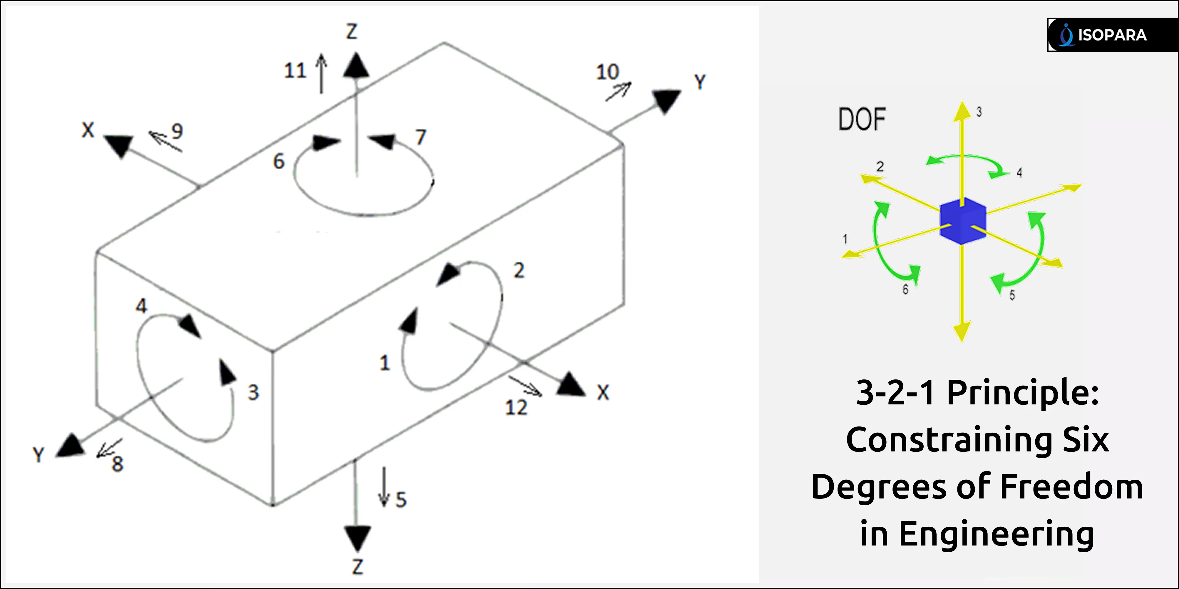
The primary goal of a DRF is to lock down these movements in a way that mimics how the part functions in its final assembly. We achieve this using the 3-2-1 principle.
3-2-1 Principle & RPS in Automotive Plastic Product Design - LinkedIn
This article from LinkedIn provides a concise, industry-focused explanation of the 3-2-1 principle and its application in automotive interiors, known as the Reference Point System (RPS).
Read the section titled "What is the 3-2-1 Principle?". Focus on how the 3, 2, and 1 points correspond to the primary, secondary, and tertiary datums and which degrees of freedom each one constrains.
Applying this to our grab handle, we must ask: How does this part assemble into the car?
- It is first brought up to the roof's inner panel or headliner support structure. The two mounting bosses make contact. This becomes our primary locating surface.
- A fastener is inserted through one hole to fix its primary position.
- A second fastener is inserted through the other hole, locking its orientation.
This sequence directly informs our datum selection:
- Primary Datum (A): The planar faces of the two screw bosses. This surface establishes the primary interface with the vehicle structure. It's a plane, so it constrains three degrees of freedom: translation along the Z-axis (up/down) and rotation about the X and Y axes (pitch and roll).
- Secondary Datum (B): The axis of one of the screw boss holes. We will designate this as the primary locating hole. Once a fastener goes through it, it constrains two more degrees of freedom: translation along the X and Y axes.
- Tertiary Datum (C): The axis of the second screw boss hole. This final point constrains the last degree of freedom: rotation about the Z-axis (yaw).
With datums A, B, and C defined, the part is fully constrained in 3D space, just as it will be in the vehicle. This DRF is the foundation for all our critical feature controls.
Controlling Critical Features: Position and Profile
With our DRF established, we can now use GD&T to control the location and form of critical features relative to it. For our grab handle, two controls are essential: Position and Profile of a Surface.
Position Tolerance
You noted a need for a "from basics" introduction to position tolerance. Simply put, position tolerance is superior to traditional coordinate dimensioning (+/-) because it defines a 3D tolerance zone within which a feature's axis or center plane must lie. For a hole, this zone is typically a cylinder.
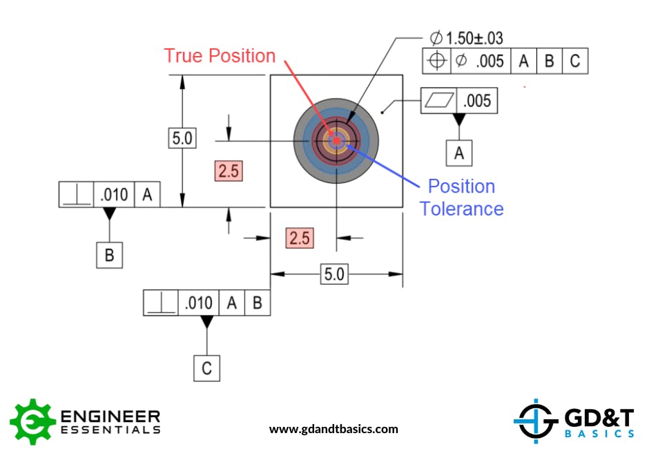
The video below gives an excellent practical walkthrough of moving from design intent to applying GD&T, including position tolerance.
How To Learn GD&T as DESIGN Engineer | Lesson 01 | MasterClass Series
This video connects the concept of design intent to the practical steps of creating a GD&T drawing. It clearly explains how to apply positional control.
Watch the segment from applying positional control. Pay close attention to: The use of basic dimensions (in boxes) to define the theoretically exact location of the hole. The explanation of the cylindrical tolerance zone and how it controls both location and the perpendicularity of the hole's axis relative to the primary datum.
For our grab handle, we would apply a position tolerance to the two screw boss holes. The feature control frame would look something like this:
| ⌖ | ø0.5 Ⓜ | A | B | C |
|---|
This communicates to the manufacturer: "The axis of this hole must lie within a cylindrical zone of 0.5mm diameter, at Maximum Material Condition (MMC), relative to the datum reference frame established by A, B, and C."
Profile of a Surface Tolerance
Injection molded parts often have complex, organic surfaces. Dimensioning these with hundreds of +/- coordinates is impractical. The Profile of a Surface tolerance is the modern, effective solution. It defines a uniform 3D tolerance boundary that envelops the surface.
This control is critical for two areas on our grab handle:
- The Class-A Surface: To ensure consistent gap and flushness with the vehicle headliner, we apply a profile tolerance to the entire visible surface, referencing our A-B-C datum frame.
- The Cantilever Snap-Fit: The precise geometry of the snap-fit hook and undercut is essential for its function. A profile tolerance ensures these features are formed correctly relative to the main body of the part.
Injection Molding Tolerance Standards: ISO 20457, DIN 16742, SPI ...
This professional guide discusses tolerancing for molded parts and highlights the importance of GD&T.
Read the sections "ISO vs. GD&T: When to Step Up" and the FAQ "When should I use GD&T instead of ± tolerances on plastic parts?". These sections reinforce why Profile of a Surface is the mandatory choice for controlling complex surfaces on a part like our grab handle.
Assembling the Final 2D Drawing
A complete automotive drawing is more than just views and dimensions. It's a technical and legal document. Here is the professional workflow to create one for our grab handle:
-
Create Necessary Views:
- Main Views: Front, top, and side views.
- Section Views: A section through the screw bosses to clearly dimension them and show wall thickness. Another section through the snap-fit feature is essential.
- Detail View: A detail view of the snap-fit hook might be needed to clearly apply dimensions and controls.
-
Establish the Datum Reference Frame:
- Apply the Datum Feature Symbol (a letter in a square frame connected to the feature) to the surfaces and holes we identified as Datums A, B, and C. The video below shows a clear example of how datums are applied and used to control other features.
GD&T : Applying GD&T scheme to a part in assembly - Hinge bracket
This video provides a very clear, step-by-step example of defining a datum scheme and applying position tolerance to control features based on assembly function. Although it's a sheet metal part, the logic is identical.
Watch these key segments: - Datum A: The primary resting face. - Datum B: The primary locating hole. - Datum C: The secondary holes, controlled as a pattern relative to A and B. - Controlling the pinhole: See how the final critical feature is controlled relative to the full A-B-C datum frame.
-
Apply GD&T and Dimensions:
- Apply Position tolerance to the screw boss pattern. Use basic dimensions to define their true position.
- Apply Profile of a Surface tolerance to the outer Class-A surface.
- Apply Profile of a Surface to the snap-fit geometry.
- Dimension other key features like overall length, width, and wall thickness using conventional +/- tolerances.
-
Complete the Drawing Notes:
This is a critical step. The notes block sets the general rules for the entire part.
Injection Molding Tolerance Standards: ISO 20457, DIN 16742, SPI ...
This resource provides an excellent checklist and templates for what should be included in a professional drawing for a molded part.
Review the sections "How to Tolerance a Molded Part Drawing: The Professional Workflow," focusing on the steps for "Define Functional Datums" and "Molding-Specific Notes." Also, look at the "2D Tolerance Note Block" under the downloadable templates.
Based on this, your notes block for the grab handle drawing should include:
- Material: PC/ABS, Molder-Specific Grade TBD (e.g., Covestro Bayblend T85 XF)
- Surface Finish: VDI 3400 Ref 27 on all Class-A surfaces shown.
- General Tolerances (unless otherwise specified): ISO 20457-TG6
- Flash: Maximum 0.1mm allowable flash at parting line in non-cosmetic areas. No flash permitted on Class-A surfaces.
- Inspection: All dimensions to be measured after parts have been conditioned for 48 hours at 23°C +/- 2°C and 50% +/- 5% relative humidity.
- All datum features and features with GD&T controls are considered Critical to Quality (CTQ).
By following these steps, you create an unambiguous set of instructions that ensures the parts you receive can be assembled correctly and meet the customer's quality expectations.
Conclusion
Today we've brought together the entire design process for the grab handle. We translated our understanding of the part's function into a robust datum scheme using the 3-2-1 principle. We then used GD&T controls like Position and Profile to manage variation in critical features identified during our DFM and DFMEA. Finally, we outlined the components of a complete, professional 2D drawing—the ultimate deliverable that communicates our design intent to the wider world of manufacturing.
Key Takeaways:
- Drawings Communicate Intent: A 2D drawing with GD&T is not just a picture; it's a set of instructions that controls how a part fits and functions.
- Datums Anchor Everything: The Datum Reference Frame (DRF) is the foundation of any good GD&T scheme. It must be based on the part's real-world assembly and function.
- Use the Right Tool for the Job: Position tolerance is ideal for controlling patterns of features like holes. Profile of a Surface is essential for controlling the complex shapes common in plastic parts.
- Notes Matter: The drawing's general notes set the context for material, finish, and inspection, preventing ambiguity and disputes.
This lesson completes Day 2 of our course. You have now taken a component from initial concept through material selection, detailed design, risk analysis, and finally, to a complete manufacturing drawing. In our next module, we will escalate the complexity by tackling a multi-part interior trim assembly and addressing an Engineering Change Order (ECO). The rigorous approach to design and documentation you've practiced here will be indispensable.
Can't find a good explanation? Sign up and we'll make it for you
Sign up