
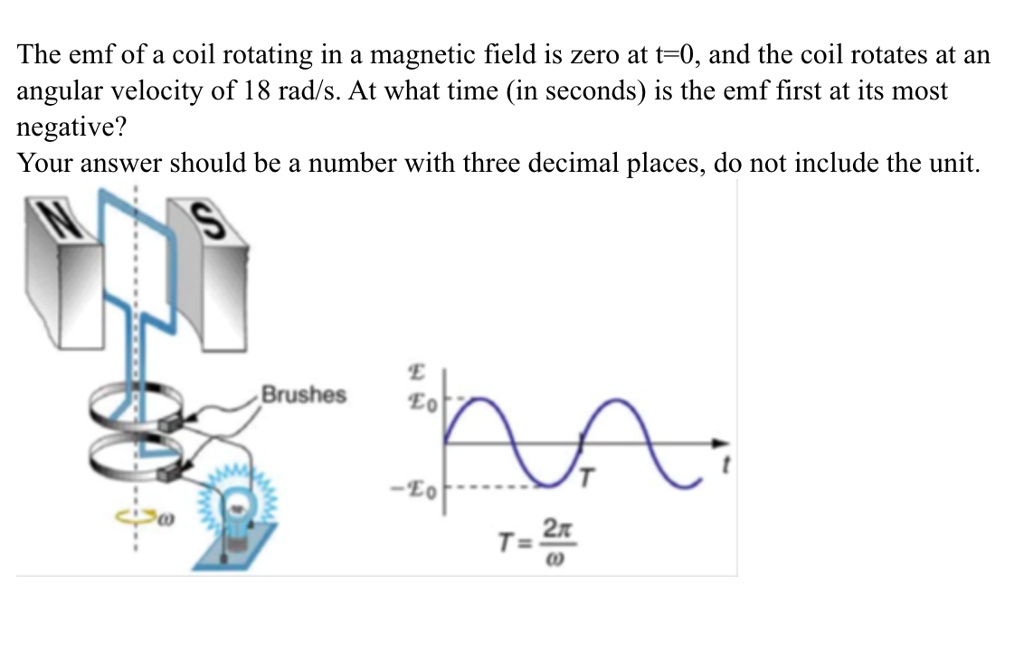
Hello! In our last lesson, we established the fundamental principle of AC generation, deriving the equation for the sinusoidal EMF produced by a rotating coil: . We now know why the voltage is sinusoidal.
Today's lesson focuses on the quantitative aspects of this process, directly addressing the learning outcome: Calculate the EMF generated by a rotating coil, relating its frequency and amplitude to rotational speed and coil geometry. We will dissect the generator equation to understand how the physical characteristics of the generator determine the voltage and frequency of the electricity it produces. This is the bridge from theoretical principle to practical engineering.
Deconstructing the Generator Equation
Let's start with the result from our previous lesson:
This equation describes the instantaneous EMF () at any time . We can separate it into two main parts:
- The Amplitude (Peak EMF): The term is constant for a given generator operating at a steady speed. It represents the maximum value of the EMF.
- The Time-Varying Part: The term describes the sinusoidal oscillation of the EMF over time.
Amplitude: The Peak EMF ()
The amplitude of the generated voltage is arguably the most important parameter. We denote it as or .
This simple product tells us everything we need to know about how to design a generator for a specific voltage output. Let's break it down:
- (Number of turns): The more loops of wire in the coil, the larger the induced EMF. This is because the EMFs from each turn add up in series. Doubling the turns doubles the peak voltage.
- (Magnetic Field Strength): A stronger magnetic field (measured in Teslas, T) results in a greater magnetic force on the charges in the wire, inducing a higher EMF.
- (Area of the coil): A larger coil area (in m²) means it "catches" more magnetic flux for a given field strength, leading to a greater change in flux as it rotates, and thus a higher EMF.
- (Angular Velocity): This is the speed of rotation, measured in radians per second (rad/s). The faster the coil spins, the more rapidly the magnetic flux changes, inducing a proportionally higher EMF.
The following video section provides a concise recap of this derivation and clearly identifies the peak EMF term.
EMF & flux equation (& graph) of AC generator | Electromagnetic induction | Physics | Khan Academy
Let's revisit the Khan Academy video from our last lesson. This time, focus on how the final equation for EMF is structured and how the peak EMF term is identified.
Please watch from 06:02 to 08:04. Pay attention to how the term E-naught (our \mathcal{E}_{peak}) is defined as NBA\omega and represents the maximum induced EMF.
This relationship is fundamental to generator design. If you need a higher voltage, you can spin the generator faster, use a stronger magnet, increase the coil area, or add more turns of wire.
Frequency and Period
The time-varying part of the equation, , determines the frequency of the alternating current. The angular velocity not only affects the amplitude but also dictates how quickly the voltage oscillates.
In practical applications, we usually talk about frequency in Hertz (Hz), which is cycles per second, rather than angular velocity in radians per second. The relationship is straightforward:
This shows that the electrical frequency of the AC output is directly proportional to the mechanical rotational speed of the generator. This is why power grids must maintain a precise generator speed to ensure a stable mains frequency (e.g., 50 Hz in Europe, 60 Hz in the Americas).
The period of one full cycle is the reciprocal of the frequency:
A Worked Example
Let's put this all together with a practical calculation. The following video walks through a complete example, from converting rotational speed into standard units to calculating the peak voltage.
Physics 45 Electromagnetic Induction: Faraday's Law (4 of 4) Rotating Loop Conductor
In this video by Michel van Biezen, you'll see how to apply the peak EMF formula to a generator with specific physical parameters.
Watch the video from the beginning to 06:46. Observe how he first converts the rotational speed from rotations per second to radians per second. Then, follow his application of the EMF formula to find the peak voltage produced by the rotating loop.
As the video demonstrates, the process is:
- Ensure all parameters are in SI units (m, m², T, rad/s). A common first step is converting from revolutions per minute (rpm) or Hz to rad/s.
- To convert from rpm to rad/s:
- To convert from Hz to rad/s:
- Calculate the peak EMF using .
- Write the full expression for the time-dependent EMF as .
For a more detailed textual reference and another worked example, you can consult the following resource.
The 'Physics Bootcamp' resource provides a concise textual derivation and a helpful worked example.
Please read from the beginning of the text, focusing on Equation 38.18, which is our main EMF formula. Then, study 'Example 38.36. Induced EMF in a Rotating Ring...' to see another application of these calculations, this time starting from a frequency in Hz.
Test your understanding!
A generator has a 500-turn coil with a diameter of 8.00 cm. It rotates in a 0.250 T magnetic field. At what angular velocity, in rpm, will its peak voltage be 480 V?
Show answer
First, we need to rearrange the peak EMF formula to solve for :
Next, let's gather our values in SI units:
- V
- T
- The diameter is 8.00 cm = 0.08 m, so the radius is m.
- The area is .
Now, plug these into the formula for :
The question asks for the answer in rpm. We need to convert from rad/s to rpm:
So, the generator must spin at approximately 7300 rpm to produce a peak voltage of 480 V.
Conclusion
In this lesson, we moved from the theoretical derivation of the generator EMF to its practical calculation. We have quantified how the physical design and operating speed of a generator determine its electrical output.
Key Takeaways:
- The amplitude, or peak EMF, of a generator is given by . It is directly proportional to the number of turns (), magnetic field strength (), coil area (), and angular velocity ().
- The frequency () of the AC voltage is determined solely by the rotational speed: .
- By manipulating these parameters, a generator can be designed to produce a desired voltage and frequency.
Preview of the Next Lesson:
We now know how to calculate the electrical output of a generator. But what about the input? Spinning the coil requires mechanical work. In the next lesson, we will investigate the relationship between the mechanical work required to turn the generator and the electrical energy it produces, applying the principle of conservation of energy. This will lead us to the important concepts of back torque and generator loading.
Can't find a good explanation? Sign up and we'll make it for you
Sign up