
Hello. The previous lesson established that ribs, gussets, and bosses need to remain thin enough at their roots to prevent sink and read-through. That geometry still has to come out of a mold reliably. Draft is what gives the moving tool steel clearance during opening and ejection, while preserving a controlled part shape.
In this lesson, you will determine a defensible minimum draft angle per face by combining four inputs: the mold pull direction, the feature’s draw depth, the intended surface finish or texture, and the shrinkage and ejection behavior of the selected polymer. The output is not merely a CAD angle: it is a documented DFM requirement tied to a named tool direction, surface specification, and supplier-confirmation status.
Draft is clearance designed into the part
A draft angle is a deliberate taper on a surface that lies generally parallel to the direction in which mold steel withdraws. Without that taper, the cooling plastic can rub, vacuum-lock, or shrink tightly against the core or cavity during mold opening and ejection. The consequences include scuffing, drag marks, ejector-pin damage, part distortion, mold wear, and—in severe cases—a part that does not release.
The supplied Draft-angle examples image makes the core point visible: straight walls may look correct in an orthographic CAD view, but they leave no clearance for ejection. The corrected forms taper by at least , including internal walls and ribs.
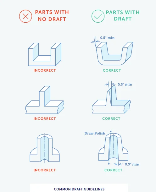
Draft is specified per surface, not divided across opposite faces. If a rib has draft on each of its two long faces, each face is inclined by relative to the pull direction.
The design question is therefore not, “Does this part have draft?” It is:
For each molded face, what minimum taper is needed to clear its particular tool surface, at its full draw depth, with the selected resin and surface finish?
Start with the pull direction, not with a generic angle
Draft has no meaning until you define the mold pull direction. For a simple housing, this is often the normal direction to the largest opening. For an interior trim component, it may be set by the Class-A surface, the intended parting line, and the need to protect visible surfaces. A complex part can have more than one pull direction because side actions may form local openings, but begin by establishing the primary opening direction.
For every near-vertical face, identify:
- Which mold half forms the face. Is it cavity-side steel, core-side steel, or a local slide?
- How that steel moves away from the part. The surface must gain clearance in that actual withdrawal direction.
- Whether the part is intended to remain on the ejector side. The part should normally stay with the half containing the ejector system, but shrinkage, surface area, and texture can alter retention behavior.
- The neutral location for the taper. This is often the parting line, but it may instead be a functional interface plane or a controlled datum plane.
- The draw depth. Measure the distance parallel to the relevant pull direction, from the start of engagement to the last point at which steel contacts the part.
A face with positive draft clears the relevant tool steel during withdrawal. A face with negative draft traps that tool steel and is an undercut relative to that pull direction. Adding more positive draft cannot solve a genuine undercut; the design needs a different parting strategy, a shutoff, a side action, or a geometry change.
This distinction is important when reviewing a CAD draft-analysis plot. A face shown as “drafted” is not automatically manufacturable unless the analysis used the correct pull direction and the taper sign matches the tool surface that forms it.
Design for Moldability, Part 1 - Design Considerations
Watch the draft explanation in Design for Moldability, Part 1 – Design Considerations from Xcentric Mold & Engineering. It shows why a part can stick to either the cavity or core and gives useful baseline values before you apply the more detailed selection method below.
Watch draft fundamentals for the connection between draft, sticking, vacuum effects, ejector damage, and textured surfaces. Then watch depth guidance, which explains why deeper surfaces generally need more taper. Treat its rule of thumb as an early feasibility screen, not as a released tooling specification.
The four drivers of a minimum draft requirement
A practical draft decision starts from a baseline and then raises the requirement whenever another driver makes ejection more difficult. Four drivers matter most.
1. Pull direction and steel ownership
A smooth outside wall formed by cavity steel and an internal wall formed by a core can look geometrically similar, yet their ejection risks differ. Internal walls often shrink onto the male core. External walls may drag in the cavity, especially when they carry texture or a large cosmetic surface area.
Draft should therefore be defined in a feature register with a statement such as:
ECU-BASE-OUTER-WALL-03: minimum cavity-side draft relative to main pull direction , measured from the parting line.
That statement is much more useful than a drawing note saying only “apply draft.”
2. Draw depth
Longer contact surfaces produce more rubbing area and more opportunity for shrinkage-driven gripping. The taper also changes the feature’s final dimensions more significantly as depth grows.
For one drafted face with draw depth and draft angle , the lateral offset is approximately:
For two opposing walls both drafted symmetrically, the total width change is:
Consider a wall with:
At draft per side:
At draft per side:
Across opposite walls, the latter changes the width by roughly . This is why draft has to be considered during package design—not added late as a cosmetic correction.
Deep, thin features create a second problem: draft can make the feature tip too thin. For a rib drafted on both long faces:
Using the previous lesson’s example:
gives:
That is usually feasible. At a much higher draft angle, however, the tip can become difficult to fill or too weak. The response is not automatically to make the rib root thicker, because that may violate the sink-control rule. You may need to reduce rib height, alter the load path, change the feature layout, or specify texture only where it is truly needed.
3. Surface finish and texture
Texture is one of the strongest draft drivers. A textured mold surface contains microscopic peaks and valleys that mechanically resist sliding during ejection. What feels like a shallow visual grain on the finished door trim is a field of tiny engagement features to the molded polymer.
[PDF] Eastman polymers processing and mold design guidelines
Read the mold-finishing and draft guidance from Eastman. It links polishing direction, texture depth, ejection force, and the risks of specifying zero draft.
On page 24, read the subsection “Texturing mold surfaces,” beginning with the texture rationale. Focus on the stated texture-depth range and the added-draft guidance. Then, on page 25, read “Draft angle guidelines,” beginning with the baseline recommendation through the discussion of zero draft. Note that these are molding guidelines for Eastman materials, so a supplier must still approve the final value for the selected grade and tool.
Eastman’s guidance provides a useful planning rule:
Suppose an exterior trim wall has a specified texture depth of:
The texture allowance is:
If the smooth-wall baseline is , the preliminary range becomes:
per face. That large value is plausible for a textured automotive trim wall and shows why styling, texture choice, and tooling direction must be decided together.
Do not use a texture category such as “light grain” as a complete requirement. Record the actual texture standard and code—for example, a customer-approved Mold-Tech, VDI, SPI, or other texture specification—plus its depth and supplier-required draft. A texture supplier’s approved tool-data sheet overrides generic planning rules.
4. Polymer shrinkage and ejection behavior
As thermoplastic resin cools, it shrinks. When a feature is molded around a core, shrinkage can tighten the part’s grip on that core. Materials differ not only in nominal shrinkage, but also in stiffness, friction, filler content, fiber orientation, abrasion, mold-temperature sensitivity, and moisture behavior.
Draft Angle Guidelines for Injection Molding - Fictiv
Read Fictiv’s draft guide as a practical comparison of material, depth, surface finish, and mold-design effects. Its tables are useful concept-stage references, but should not replace resin-grade data or a toolmaker’s feasibility review.
Under “Draft and Injection Molding Materials,” read the shrinkage explanation, then inspect the material table immediately below it. Under “Draft and Part Features,” read the feature-depth introduction and examine the lookup table. Finally, under “Draft and Surface Finishes,” read the texture discussion. Finish with “Draft Direction and Injection Mold Design,” focusing on why draft direction and core-side ejection must agree.
The material table in that guide illustrates the principle rather than providing a universal release rule:
| Material family in the guide | Listed minimum draft | Listed recommended draft |
|---|---|---|
| Nylon | ||
| Polyethylene | ||
| Polypropylene | ||
| Polycarbonate |
The critical engineering interpretation is this: a table’s listed minimum is not a design target. Eastman explicitly warns that zero draft can lock the mold during ejection. Use at least a positive baseline unless the toolmaker has approved a tightly controlled exception with a specific ejection method.
For the components in this course, the resin grade matters more than the polymer-family label:
- PP-TD20 door-trim carrier: begin with a positive smooth-wall draft, typically within the to concept range, then increase it for texture, deep draws, and the actual filled grade’s supplier data.
- PA66-GF30 ECU housing: do not assume unfilled-nylon behavior applies. Glass reinforcement can make the material more abrasive and can create directional shrinkage effects. Use the approved resin supplier’s molding guide and tooling feedback.
- HVAC outlet components: different pieces can have different requirements. A smooth internal airflow surface, a visible textured bezel, and a narrow pivot boss should not all inherit one global draft value.
A disciplined method for selecting the minimum
Use the following sequence during concept and CAD development.
Step 1: Create a pull-direction map
For each part, establish the main pull direction and identify faces formed by:
- cavity steel;
- core steel;
- shutoffs;
- side actions;
- collapsible or special cores, if any.
At this stage, do not attempt to resolve every tool detail. Your goal is to show that each face has a credible release direction.
Step 2: Divide the part into draft zones
A single component usually needs several draft specifications. Typical zones include:
| Zone | Typical example | Main draft drivers |
|---|---|---|
| Visible exterior wall | Door-trim Class-A return | Texture, cosmetic scuffing, draw depth |
| Smooth internal wall | ECU inner enclosure wall | Core retention, shrinkage, deep draw |
| Rib or gusset | B-side stiffener | Thin tip after draft, local ejection |
| Boss or tubular core | Screw boss or pivot | Core grip, bore geometry, ejection |
| Shutoff face | Opening or stepped parting line | Steel durability, sealing, toolmaker rule |
| Sealing or precision interface | ECU gasket land | Function and dimensional control, not merely release |
Do not put texture on a critical gasket land simply because the adjacent exterior surface is textured. Similarly, do not force the Class-A draft requirement onto hidden ribs that have no texture but must retain a practical tip thickness.
Step 3: Set the smooth-surface baseline
For ordinary molded walls, use:
as a sound starting point. Eastman identifies per side as its general recommendation. For short ribs, bosses, and constrained small features:
can be an initial lower bound, provided the material, feature depth, tool finish, and ejection strategy support it.
Treat these values as baseline screens, not release criteria:
| Condition | Preliminary draft approach |
|---|---|
| Smooth general wall | Start at per side |
| Deep wall or difficult core release | Increase above baseline |
| Short smooth rib or boss | minimum per side, then check tip thickness and depth |
| Visible textured wall | Smooth-wall baseline plus texture allowance |
| Deep textured Class-A wall | Supplier-confirmed value; often substantially above |
| Zero draft | Redesign or obtain explicit toolmaker exception approval |
Step 4: Add the texture requirement
For a textured surface, calculate the planning value:
Use the conservative end of the texture allowance when the wall is deep, highly cosmetic, or formed by a texture-sensitive cavity surface.
Step 5: Check depth and remaining thickness
Use the draft geometry equations to inspect:
- change in external package dimensions;
- change in internal clearances;
- rib and boss tip thickness;
- required clearance to nearby mating parts;
- distortion of a sealing land or datum surface;
- whether a deep texture requirement creates an unrealistic shape.
If a draft requirement conflicts with package space, do not quietly reduce the angle. Escalate the conflict to the component design review with alternatives such as a revised parting line, shallower texture, a split component, a different surface treatment, or tooling with a side action.
Step 6: Apply the material-grade adjustment
Check the selected resin’s supplier documentation for:
- mold shrinkage range and test method;
- recommended draft;
- filler type and filler percentage;
- surface-finish limitations;
- drying and molding conditions;
- known release, scuffing, or core-grip issues.
Material data should refine your provisional design value. It does not remove the need to consider texture and depth.
Step 7: Obtain supplier feasibility confirmation
At a release-ready stage, the molder or toolmaker confirms draft in the context of real tooling details:
- cavity and core finish;
- cooling layout;
- gate location;
- part retention and ejector layout;
- expected shrinkage;
- tool steel selection;
- texture supplier’s requirements;
- dimensional tolerance and inspection requirements.
A value is ready to release only when that evidence is linked to the controlled CAD and drawing revision.
Worked example: textured door-trim return flange
Assume a visible door-trim return wall is molded in PP-TD20 with an assumed light photo-etched grain. The nominal wall is:
The draw depth along the main tooling axis is:
The surface texture depth is provisionally specified as:
Baseline
For a smooth PP surface, select a preliminary baseline:
Texture addition
Using the Eastman planning rule:
Therefore:
per face.
Packaging impact
At the lower end:
At the upper end:
That is a significant dimensional change. If two opposing return walls draft symmetrically, the distance between them changes by roughly to over the full depth.
The correct concept-stage conclusion is:
A to per-side draft is required provisionally for this -deep textured wall. Confirm the final value with the texture supplier and molder. Verify that styling surfaces, attachment features, mating trim, and nominal gap-and-flush targets can tolerate the resulting taper.
This is a better conclusion than choosing because it is convenient in CAD, then discovering drag marks or a texture-release problem after tooling design.
CAD implementation and evidence
In Onshape, make draft a controlled parameter rather than a late direct edit. Define named variables or a companion DFM table, such as:
| Variable | Example | Meaning |
|---|---|---|
main_pull | Primary mold-opening direction | |
draft_smooth | General smooth-wall baseline | |
draft_feature_min | Minimum for qualifying short ribs and bosses | |
texture_depth | Assumed approved texture depth | |
draft_texture_min | Preliminary textured-wall requirement | |
tooling_status | Open | Molder confirmation state |
Model features from stable reference planes, define a neutral plane or parting reference deliberately, and apply draft using the designated pull direction. Then inspect the results with section views and draft analysis. In CATIA V5 or 3DEXPERIENCE CATIA, the equivalent intent is a published tooling axis, controlled Part Design Draft features, and a Draft Analysis using the same declared direction.
Record each critical zone in a Draft and Tooling Direction Register:
| Field | Example entry |
|---|---|
| Feature ID | DTC-CLASSA-RETURN-012 |
| Part and revision | Driver-door trim carrier, Rev A |
| Forming steel | Cavity side |
| Pull direction | Main pull |
| Draw depth | |
| Material | PP-TD20, grade confirmation open |
| Surface requirement | Light photo-etched grain, code pending |
| Baseline draft | per side |
| Texture addition | to |
| CAD draft applied | per side |
| Evidence | Draft-analysis image, section, texture inquiry |
| Open risk | Confirm final texture depth and molder approval |
| Linked change record | DFM action or ECO identifier |
This record supports the PLM discipline you are building throughout the course. If trial parts later show scuffing, sticking, texture drag, or an unacceptable package change, the supplier issue and resulting ECO can trace directly to the original draft assumptions, CAD version, mold-flow evidence, and final released decision.
A fast review checklist
Before sharing CAD for supplier DFM review, verify the following:
- Every drafted face has an identified forming tool surface and pull direction.
- Draft is stated per side, with the neutral plane or parting reference understood.
- Draw depth is measured along the actual tool movement direction.
- Smooth walls start from a positive baseline, normally around per side.
- Short ribs and bosses use at least per side unless supplier evidence requires more.
- Textured surfaces include a texture-specific draft allowance.
- The selected resin grade—not only the generic polymer family—has been considered.
- Ribs and bosses retain adequate tip thickness after draft.
- Package dimensions, mating interfaces, and visible styling surfaces remain feasible after taper.
- Zero-draft and negative-draft areas are explicitly escalated rather than hidden in the model.
Key takeaways
Draft is an ejection and tooling requirement, not a cosmetic taper added after the model is complete.
- Define the pull direction and identify which tool steel forms each critical face before choosing an angle.
- Use per side as a practical smooth-wall baseline, with per side as a lower concept-stage bound for qualifying short ribs and bosses.
- Increase draft as draw depth increases and as a feature becomes harder to eject.
- For texture, add draft based on the actual texture depth and supplier specification. Eastman’s planning guidance is to per of texture depth.
- Polymer shrinkage and grade-specific behavior affect core grip and ejection. Generic material tables help at concept stage, but resin supplier data and molder approval control the final decision.
- Check the geometry created by draft: it changes package dimensions, internal clearance, and rib or boss tip thickness.
- Capture pull direction, draw depth, finish, polymer, applied draft, evidence, and unresolved risks in a controlled DFM record.
Next, you will use these geometry and tooling fundamentals to diagnose likely injection-molding defects—sink, weld lines, short shots, air traps, shrinkage, and warpage—from part geometry, gate strategy, and process conditions.
Can't find a good explanation? Sign up and we'll make it for you
Sign up