
Hello. This module moves from plastic-part design rules into the CAD and configuration architecture that makes an assembly maintainable through design reviews, supplier input, and engineering changes.
For the three assumption-based EDV projects, treat CAD organization as part of the engineering definition—not as file housekeeping. A housing base, cover, gasket, connector, and fasteners may physically assemble into one unit, but they have different owners, interfaces, sourcing routes, verification evidence, and revision histories. The CAD structure needs to make those distinctions visible and controlled.
By the end of this lesson, you will be able to set up a practical Onshape structure for a multi-part plastic assembly, establish a meaningful version-and-release baseline, and translate the approach into CATIA V5/V6 and ENOVIA language.
1. Start with the product structure, not the feature tree
Consider an assumed high-voltage ECU enclosure for the EDV projects. Its early engineering bill of materials (EBOM) might include:
| Level | Engineering object | Example part number | Ownership / source |
|---|---|---|---|
| 0 | ECU enclosure assembly | EDV-ECU-1000 | Design engineering |
| 1 | Molded housing base | EDV-ECU-1100 | Plastic supplier |
| 1 | Molded cover | EDV-ECU-1200 | Plastic supplier |
| 1 | Gasket | EDV-ECU-1300 | Sealing supplier |
| 1 | Thread-forming screws | STD-M5-XXXX | Approved standard part |
| 1 | PCB assembly | EDV-ECU-1400 | Electronics team or supplier |
| 1 | Connector / vent | SUP-ECU-XXXX | Purchased component |
This hierarchy is not yet an MBOM. The EBOM answers: what does the design require? An MBOM later answers: what must the plant or supplier procure, mold, assemble, inspect, and package? Keep the distinction even when the initial structures look similar.
In Onshape, a useful organizing principle is:
- A Document is the collaborative and controlled project container.
- A Part Studio is where related geometry and physical parts are created.
- An Assembly represents occurrences of those parts and their mating relationships.
- A Drawing communicates released manufacturing and inspection requirements.
- A Version is an immutable snapshot of a document at a defined point in its history.
- A Release is a controlled authorization to use a defined revision, subject to the account’s configured workflow and permissions.
The key design decision is not “one document or many?” It is: which geometry must change together, and which items must be independently controlled?
Read Onshape’s “Documents” help page to understand the document as a controlled design container, then focus on the practical rules for deciding when to separate data and how document versions support baselines.
In the opening explanation, read the document model. Notice that Part Studios, assemblies, drawings, imports, and supporting files can coexist as tabs within one document. Then, under “Managing document versions and history,” read the version guidance. Focus on the difference between editable history and a read-only version. Finally, under “Best practices and strategies,” read the organization rules. Pay particular attention to reusable and purchased components.
2. Part Studios: organize around geometric dependency
A common beginner pattern is to put the entire assembly into one Part Studio because it is initially convenient. That can work for a small, highly interdependent mechanism, but it becomes difficult to manage once different components are reviewed, supplied, changed, and released separately.
A Part Studio is not equivalent to one production part. It is a modeling environment. One Part Studio can contain multiple bodies, but that does not make those bodies one part number or one released item.
How to use Part Studios Most Efficiently
Watch “How to use Part Studios Most Efficiently” by Onshape for a compact explanation of when multi-part top-down modeling is useful and why it remains distinct from assembly work.
Watch top down modeling to see why directly related components may belong in one Part Studio during early design. Then watch Part Studio versus assembly for the essential distinction: model geometry in the Part Studio; instantiate, mate, and assess the product in the Assembly.
For an ECU enclosure, use the following decision rule.
| Situation | Preferred Onshape approach | Reason |
|---|---|---|
| Shared vehicle hardpoints, package envelope, connector keep-outs, sealing plane | One master-layout Part Studio | These references define the assembly interface and should have one authoritative source. |
| Housing base and cover at early concept stage, with directly coupled sealing geometry | One multi-part Part Studio can be justified | A change to the sealing perimeter can update both bodies together. |
| Base and cover approaching separate supplier release | Separate Part Studios driven by the master layout | Each molded component gains a cleaner feature history and more independent change control. |
| Gasket, vent, connector, fasteners, PCB | Separate Part Studios or linked standard/supplier content | They are controlled as distinct engineering items and should not be recreated casually. |
| Whole ECU enclosure | Assembly tab | This is where instances, mates, access, clearance, and BOM structure are evaluated. |
The practical test is simple:
Put parts in the same Part Studio only when their geometric relationship is so strong that separating them would create duplicated dimensions or fragile references.
Do not use a single Part Studio merely because the parts are assembled together. Conversely, do not split every feature into a separate document if it creates a web of uncontrolled external references.
Part Studios - https : / / cad . onshape . com
Read the relevant portions of Onshape’s “Part Studios” documentation to establish the Part Studio as a shared-reference environment, then connect its part metadata to the PLM structure you will use throughout the course.
Under “Part Studio basics,” read the definition. Distinguish the modeling environment from the parts it produces. Next, read the paragraph immediately following that section’s toolbar discussion, beginning the performance guidance. Focus on the recommendation to use derived parts or in-context modeling when references are needed across Part Studios. Finally, in “Editing and resetting part properties,” read the identification fields. Note the distinct purposes of Part number, Revision, and State.
3. A robust Onshape architecture for a plastic assembly
For the course projects, begin with one document per design project or subsystem, then split into linked documents only when reuse, supplier boundaries, or performance justify it.
Use an explicitly assumption-based name. Do not imply that it is a real Rivian, Amazon, or supplier data set.
Recommended starting document
Document name
EDV_ASSUMPTION_HV_ECU_1000
Document description
“Training project. Assumption-based ECU enclosure architecture. No proprietary vehicle geometry or requirements represented.”
Suggested tab and folder structure
| Folder / tab name | Type | Purpose |
|---|---|---|
00_Control | Folder | Baseline notes, imported assumptions, review evidence, reference images |
PS_00_Master_Layout | Part Studio | Vehicle coordinates, mounting points, package envelope, keep-outs, connector approach directions |
PS_10_Housing_Base | Part Studio | Base walls, ribs, bosses, inserts, vehicle mounts, sealing land |
PS_20_Housing_Cover | Part Studio | Cover walls, return flange, compression stops, cosmetic surfaces |
PS_30_Gasket_Interface | Part Studio | Gasket section, groove reference geometry, compression study geometry |
PS_40_PCB_Supports | Part Studio | PCB locators, supports, clearance envelope; use only when not integral to the base |
ASM_1000_ECU_Envelope | Assembly | Top-level engineering assembly and preliminary EBOM |
DRW_1100_Housing_Base | Drawing | Base manufacturing drawing after release readiness |
DRW_1200_Housing_Cover | Drawing | Cover manufacturing drawing after release readiness |
The tab names provide navigation and model intent. They do not replace part numbers. A tab may contain multiple parts, while a physical part must have its own part number, description, state, revision, material, and ownership data.
What belongs in the master layout
The master layout should be deliberately sparse. It is an interface definition, not a duplicate of all production geometry. Include:
- Assumed vehicle coordinate system and installed orientation.
- Mounting-hole axes and target planes.
- Maximum package envelope and defined keep-out volumes.
- Connector interfaces and harness-approach vectors.
- PCB envelope and electrical-isolation boundary.
- Sealing-plane reference and any critical alignment axes.
- Service tool and removal envelopes, where known.
For the real EDV projects, label every imported or constructed vehicle reference as one of the following:
| Confidence status | Meaning |
|---|---|
| Public reference | Based on publicly available information; not sufficient as a final production interface. |
| Engineering assumption | Created for this training project and subject to validation. |
| Controlled interface | Approved within the simulated project baseline. |
| Supplier-controlled interface | Owned by a supplier and used under a declared revision or datasheet reference. |
This prevents a polished CAD model from silently becoming an unverified claim about vehicle packaging.
Build the controlled reference chain
A mature CAD architecture should make the chain of authority apparent:
- The master layout defines the approved interfaces and package intent.
- The component Part Studios consume only the references they need.
- The assembly brings the released or review-level components together as occurrences.
- The drawing derives dimensions and GD&T from the controlled component definition.
- The baseline register records which document version and component revisions were reviewed or released.
Avoid referencing arbitrary generated faces from another part. Faces can split, merge, or disappear after a fillet, shell, draft, or tooling change. Prefer named planes, axes, sketches, mate connectors, and intentionally preserved interface geometry.
4. Guided implementation in Onshape
Set up the architecture now using simple placeholder solids if you have not yet modeled enclosure geometry. The goal is the structure and traceability, not a finished ECU design.
A. Create the document and tabs
- Create a new document named
EDV_ASSUMPTION_HV_ECU_1000. - Rename the default Part Studio to
PS_00_Master_Layout. - Rename the default Assembly to
ASM_1000_ECU_Envelope. - Add folders for
00_Control,10_CAD,20_Assembly, and30_Drawings. - Create two additional Part Studios:
PS_10_Housing_BaseandPS_20_Housing_Cover. - Create a drawing tab only when you have a part worth documenting; avoid empty drawing tabs that can be mistaken for released evidence.
B. Create a minimal master layout
In PS_00_Master_Layout, create uncomplicated reference geometry:
- A coordinate-system convention such as vehicle , , and .
- A rectangular enclosure package envelope.
- Four nominal vehicle-mounting points.
- A sealing-plane reference.
- A connector keep-out block and an approach direction.
- A PCB-volume placeholder.
Name the references according to their function, not their construction history. For example:
MC_Vehicle_Install_OriginPLN_Sealing_InterfaceAX_Mount_FLAX_Mount_FRENV_PCB_MaxENV_Connector_Keepout
The prefix is optional, but the functional meaning is not. A name such as Plane 17 provides no information to a reviewer or engineer performing an ECO six months later.
C. Create component models from controlled references
In the base and cover Part Studios, use the master layout as the source for required interface geometry. During active development, keep reference relationships visible and documented. Before a formal review baseline, ensure that downstream references point to the intended document version rather than an uncontrolled moving target.
At this stage, simple shells or blocks are enough. Give each resulting physical part an initial part number and description in the Parts list properties:
| Part | Example part number | Initial description |
|---|---|---|
| Housing base | EDV-ECU-1100 | ECU enclosure base, molded polymer |
| Housing cover | EDV-ECU-1200 | ECU enclosure cover, molded polymer |
| Gasket | EDV-ECU-1300 | ECU enclosure perimeter gasket |
Use placeholder materials only if clearly marked as preliminary. A material selection is an engineering decision and will be addressed rigorously in the ECU project.
D. Assemble, mate, and check the preliminary EBOM
Insert the base and cover into ASM_1000_ECU_Envelope. Use assembly mates to establish the intended installed relationship. A fixed base plus named mate connectors for repeatable mounting locations is often clearer than repeatedly selecting transient edges and faces.
The assembly should answer these questions:
- Which component is the top-level product?
- Which physical parts occur in it?
- How many of each are required?
- What is fixed to the vehicle-side interface?
- Which relationships are functional, such as gasket compression direction or connector approach?
- Which components are designed, purchased, or supplier-owned?
Do not model standard screws as custom geometry unless their geometry is needed for clearance or tool-access analysis. Link or represent them as controlled standard parts instead.
5. Version, revision, and release are different controls
These terms are often blurred, especially in small teams. They should remain distinct.
| Control | What it freezes or identifies | Typical use |
|---|---|---|
| Workspace | Current editable design state | Active design work |
| Document version | Immutable snapshot of the document history | Design-review baseline, stable reference for a linked document |
| Part revision | Identifies the approved evolution of a particular part | Manufacturing, supplier, inspection, service traceability |
| Release | Formal authorization of selected objects at defined revisions | Build, procure, inspect, or communicate controlled design data |
| Product baseline | A declared collection of related revisions and evidence | PDR, CDR, DV build, PPAP submission, production release |
A version is useful evidence, but a version alone does not prove that a part is approved for production. Conversely, a release should identify the exact technical definition that was approved.
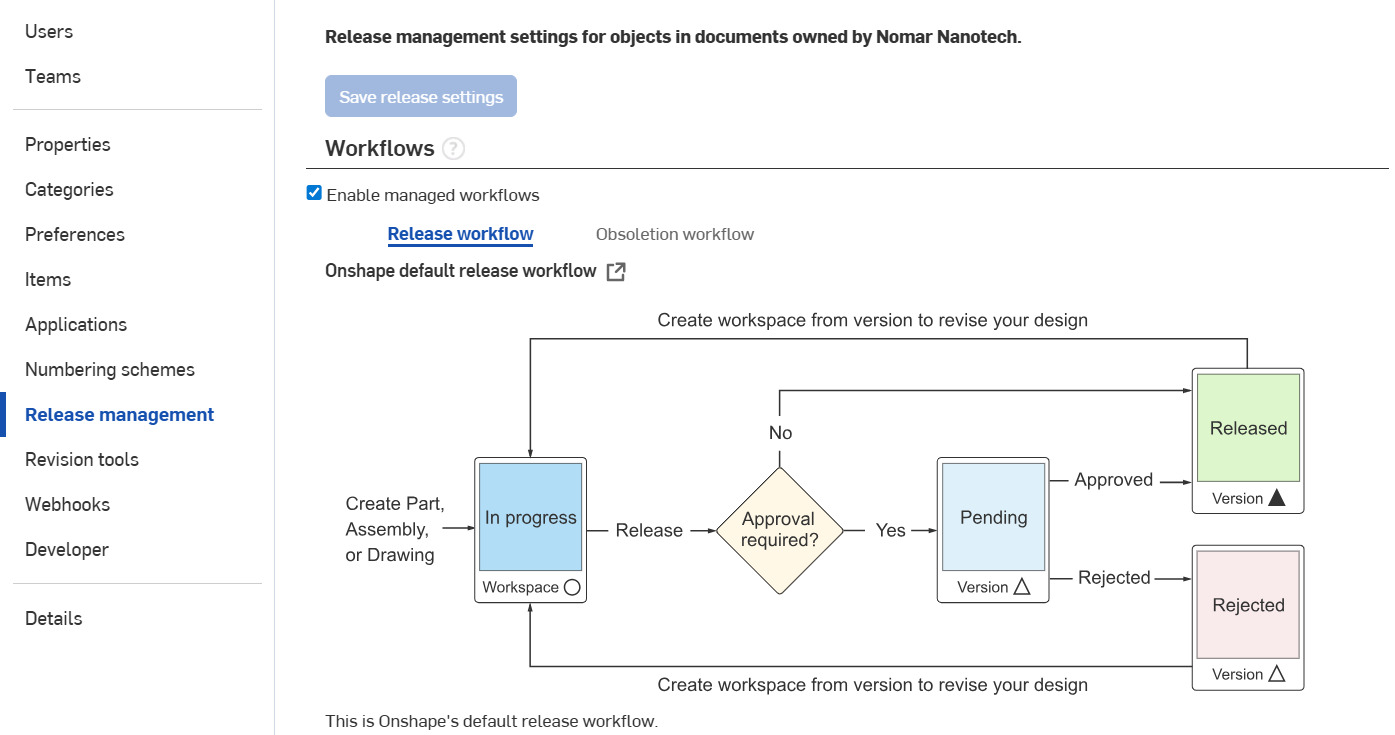
The workflow shown in the image is a useful model even if your account does not expose all managed-release capabilities. The exact available controls depend on the Onshape plan, organization settings, and permissions.
A practical baseline method
For a preliminary design review, create a read-only version with a clear name, for example:
V0.1_PDR_2025-03-08
In the version description, record:
- Scope: base, cover, gasket concept, mounting interfaces.
- Requirements baseline:
REQ-ECU-BASELINE-01. - Open risks: gasket compression not yet validated; polymer not yet selected.
- Approver or review authority.
- Decision-log identifier.
- Any linked-document version references.
If managed release is available, submit a release candidate containing the required parts, assembly, and drawings under the organization’s configured workflow. Do not release incomplete drawings merely to make the CAD appear mature.
If managed release is not available in the free account, use a controlled release register outside the model as a simulation. Record the Onshape version identifier, part number, intended revision, review decision, approval authority, effective date, and applicable ECO. Call it a simulated release record, not a released production part.
A simple controlled register may look like this:
| Baseline | Onshape version | Object | Part number / revision | State | Authority | Change reference |
|---|---|---|---|---|---|---|
| PDR-01 | V0.1_PDR_2025-03-08 | Housing base | EDV-ECU-1100 / PRE-A | Review baseline | Chief engineer simulation | Initial concept |
| PDR-01 | V0.1_PDR_2025-03-08 | Housing cover | EDV-ECU-1200 / PRE-A | Review baseline | Chief engineer simulation | Initial concept |
| REL-01 | V1.0_RELEASE | Housing base drawing | EDV-ECU-1100 / A | Released | Release authority | ECO-ECU-001 |
The important discipline is that the revision and evidence change together. A revised CAD model without an updated drawing, BOM impact assessment, approval, and change record is not a controlled change.
6. Map the structure to CATIA V5/V6 and ENOVIA
The concepts map well across systems, but they are not identical objects. In particular, a CATIA CAD file, an ENOVIA engineering item, and an MBOM part can be separate but related objects in an enterprise deployment.
| Onshape concept | CATIA V5 equivalent | CATIA V6 / 3DEXPERIENCE and ENOVIA interpretation | Important caveat |
|---|---|---|---|
| Document | Project-level CAD data container | Collaborative space or managed design context | An Onshape document is broader than one CATPart or CATProduct. |
| Part Studio | Usually a CATPart modeling context | Physical Product / 3D Shape design context, depending on deployment | A Part Studio can generate several physical parts; it is not always one-to-one with CATPart. |
| Part created in a Part Studio | CATPart or body-based part definition | Engineering item or physical product with associated 3D shape | In ENOVIA, item identity and CAD representation may be separate objects. |
| Assembly | CATProduct | Product structure / assembly product | Both represent instances and product hierarchy, not merely geometry. |
| Assembly instance | CATProduct component instance | Product occurrence / instance | One part definition can occur multiple times. |
| Mate connector and controlled reference geometry | Published interface, axis system, plane, point, or surface | Managed interface/reference depending on the application | Onshape has no direct “Publication” command equivalent. |
| Document version | Saved controlled snapshot | Baseline or revision-related snapshot | A version is not automatically a formal released revision. |
| Part number, state, revision, owner | Part/document attributes | ENOVIA attributes and maturity information | Exact attribute names are company-configured. |
| Release candidate and approval workflow | Release process around CATPart/CATProduct/CATDrawing | ENOVIA maturity route, approval, and change governance | Workflow routing, roles, and states vary by company configuration. |
| Drawing tab | CATDrawing | Managed drawing representation linked to product definition | The drawing must be revised consistently with CAD. |
CATIA publications: the interface-contract idea
In CATIA V5, a publication is a named, intentional piece of geometry exposed for use by another part or product. It might be a plane, point, axis, sketch, surface, or selected feature. Instead of letting downstream components attach to arbitrary parent geometry, they connect to this controlled interface.
For the ECU enclosure, useful CATIA publications might include:
PUB_Sealing_PlanePUB_Mount_FL_AxisPUB_Connector_A_DatumPUB_PCB_OriginPUB_Cover_Mating_Surface
This reduces the risk that a downstream link breaks when the upstream part is remodeled. More importantly, it communicates what other engineers are permitted to use as an interface.
CATIA V5: Publications Part1 #catiav5 #3dexperience #cadcam
Watch selected portions of “CATIA V5: Publications Part1” by 3D CAD Academy to refresh the mechanics and purpose of CATIA V5 publications. Treat the video’s example as an illustration of controlled interface geometry, not as a universal release-management workflow.
Watch publication purpose for the basic rationale: a named geometric interface supports associative links between components. Then watch creating and testing to see a point published, consumed in a second component, and checked after an upstream change. Focus on the architectural lesson: downstream geometry should depend on a stable named interface rather than an incidental feature.
The Onshape equivalent to a publication strategy
Onshape does not use CATIA’s exact publication object. Achieve the same engineering intent by:
- Keeping master interfaces in a dedicated layout Part Studio.
- Naming interface sketches, planes, mate connectors, axes, and surfaces by function.
- Deriving or referencing only the controlled geometry needed by downstream parts.
- Locking inter-document references to known versions before a review or release.
- Documenting interface ownership and revision status in the baseline record.
- Avoiding downstream references to cosmetic, filleted, drafted, or otherwise unstable faces.
The goal is not to replicate a CATIA command. The goal is to preserve stable, reviewable, controlled interfaces across the product structure.
7. Architecture failures to prevent early
Several avoidable patterns create disproportionate trouble during later validation and ECO work.
| Failure pattern | Why it fails | Better approach |
|---|---|---|
| Entire assembly in one Part Studio | Dense feature tree, poor performance, mixed ownership, difficult release scope | Keep only geometrically interdependent parts together; use a master layout and separate component studios. |
| One document per tiny part from day one | Excessive linking and weak visibility of product context | Start at subsystem level; split reusable, supplier-owned, or independently released content when justified. |
| Using a workspace as a supplier baseline | The geometry can change after it is shared | Share a named version and record it in the baseline register. |
| Treating a version as an approved release | Immutable does not mean authorized for build | Use the managed release workflow or a clearly marked simulated release register. |
| Using revision letters only in filenames | Relationships to CAD, drawings, BOMs, and changes become ambiguous | Store revision and state as controlled metadata and link them to the change record. |
| Referencing arbitrary faces across parts | A routine feature edit can break or misdirect the reference | Reference dedicated master geometry, named axes, planes, sketches, or mate connectors. |
| Recreating purchased parts | Creates uncontrolled substitutes and inaccurate responsibility | Link approved supplier or standard-part definitions and record source ownership. |
Key takeaways
A professional multi-part assembly begins with a controlled product structure:
- Use an Onshape Document as the project container and organize tabs around CAD, assembly, drawings, and evidence.
- Use Part Studios for parts that genuinely share geometry; do not confuse them with the physical parts they create.
- Use an Assembly to instantiate parts, define relationships, assess fit, and generate the preliminary EBOM.
- Create a sparse master layout that owns vehicle interfaces, package envelopes, hardpoints, and controlled reference geometry.
- Distinguish an editable workspace, a read-only version, a part revision, a formal release, and a multi-object baseline.
- In CATIA, use publications as stable geometric contracts. In Onshape, implement the same discipline through named master references, mate connectors, derived geometry, and version-controlled links.
- Treat ENOVIA as the governance layer that relates design representations, engineering items, maturity states, approvals, and changes—not merely as file storage.
Next, you will build on this architecture by defining a master-skeleton and published-reference strategy in more detail: what reference geometry belongs in the skeleton, how to name and consume it, and how to prevent downstream CAD from becoming fragile during iterative automotive design.
Can't find a good explanation? Sign up and we'll make it for you
Sign up